
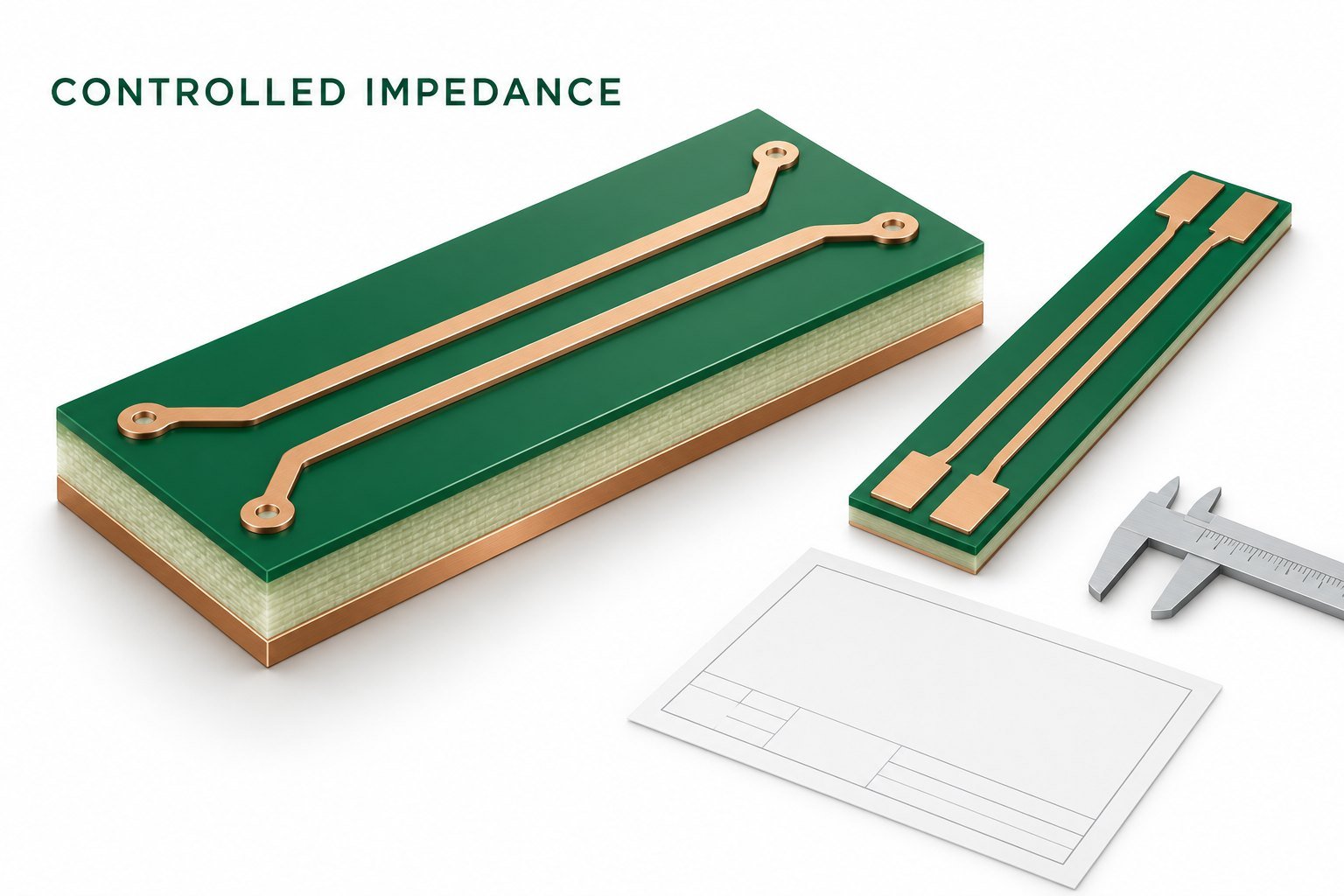
A controlled impedance PCB needs a specification that connects an electrical target to a defined physical structure and an agreed measurement. State the target and tolerance, identify the trace layer and references, describe the accepted stackup, and agree how the finished build will be verified. A trace-width value without those connections is an incomplete purchasing requirement.
The central release decision is who may change the construction or trace geometry, under what conditions, and with what evidence. That decision should be explicit before the fabricator prepares production data.
Separate the design target from the manufacturing target
Start with the interface or circuit requirement. Identify whether the requirement concerns a single-ended line, a differential pair, or another structure. Do not select a familiar nominal impedance merely because it appears in an example stackup.
Then determine what portion of the design the fabrication impedance requirement represents. A uniform trace section, a connector launch, and a layer transition are different physical objects. A coupon can provide evidence about its represented structure; it cannot establish the behavior of every discontinuity in the complete channel.
Keep system acceptance requirements separate from fabrication acceptance. A board can meet a specified coupon impedance and still require channel analysis, connector verification, or functional testing. Conversely, a system failure should not automatically be diagnosed as an impedance-manufacturing failure without checking the relevant evidence.
Describe each structure so it can be reconstructed
Create one entry for every distinct controlled structure. Identify the physical layer, reference plane or planes, trace width, relevant pair spacing, and local dielectric construction. Use the same stackup revision in the drawing and the electrical model.
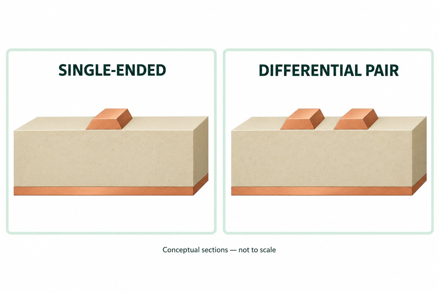
State what the dimensions mean. A nominal layout width, a finished etched width, and a manufacturing compensation are related but different records. Likewise, distinguish starting copper from finished copper and a proposed pressed dielectric thickness from an unqualified overall board thickness.
Record the material model and its source conditions. If the solver uses a dielectric value supplied for a particular method or frequency range, preserve that context. A solver result with many digits does not resolve uncertainty in the construction inputs.
Polar’s design-for-test note discusses recalculating controlled dimensions when stackup changes and examining sensitivity to build parameters. It also treats coupon design and test access as part of the manufacturing discussion. Polar Instruments: AP132, Controlled impedance—design for test
Write the acceptance schedule before quoting
The proposed schedule below is intended to be completed with the design owner and fabricator. Its blank requirements must come from the actual circuit, rather than a generic tolerance copied from another board.
| Schedule field | Required decision | Why the decision matters |
|---|---|---|
| Structure identifier | Which nets, layer, and cross-section does this entry cover? | Prevents one coupon result being assigned to unrelated geometry |
| Electrical requirement | Target, allowed range, and applicable mode | Defines the acceptance question |
| Construction | Accepted stackup revision, local dielectric, copper, and material model | Links calculation and build |
| Geometry authority | Fixed dimensions or approved adjustment process | Prevents an electrical correction from silently changing another function |
| Representation | Coupon structure, location, and relationship to the product traces | Defines what the test can establish |
| Measurement | Method, probe/fixture arrangement, evaluation region, and reporting | Makes the result interpretable and repeatable |
| Disposition | Required records and response to an out-of-range result | Prevents acceptance criteria being invented after measurement |
Where several nets share one structure, document the grouping rationale. A layer name alone may be insufficient if different regions have different surrounding copper or dielectric conditions.
Agree how the coupon will be measured
Time-domain reflectometry, or TDR, evaluates reflections along a structure using a fast electrical edge. The probe connection contributes to what the instrument observes, so test access belongs in the design discussion. Polar’s probe note explains that poor probe-to-trace connections can introduce ringing and reduce measurement quality. Polar Instruments: AP128, Choosing the best Polar IP probe
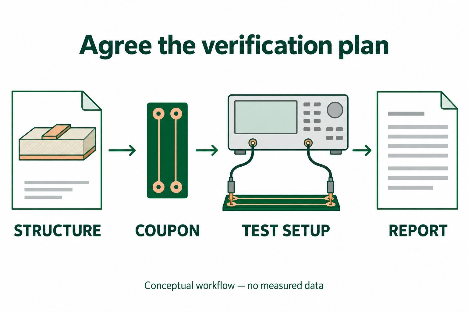
Ask the test owner to identify the evaluation region and explain how the start connection and trace end are handled. Do not assume that any displayed average is a meaningful acceptance number. The selected region should correspond to the intended uniform structure, and the measurement record should preserve that choice.
Ask what the report will contain before approving the purchase. Useful fields include the board and panel identity, coupon identifier, structure, target range, measured result, test setup reference, and disposition. Decide whether waveforms are required for the engineering objective; the answer may differ between routine production checks and a disagreement investigation.
The requested evidence should match the claim. A report labeled “impedance test passed” is less useful when nobody can identify the represented layer or the acceptance range. A detailed waveform is also insufficient if it belongs to a different construction revision.
Control proposed trace-width changes
A fabricator may propose a different width to match its offered construction. Review the proposal against the entire circuit task. A change that seems acceptable for a long uniform line may affect a coupling gap, a package escape, a delay-sensitive section, or a connector transition.
For that reason, define the allowed adjustment process rather than granting unrestricted permission to achieve one nominal target. Request the original dimension, proposed dimension, affected structures, model assumptions, and any artwork changes. If the geometry is fixed for circuit reasons, say so and require a construction proposal that respects it.
Use a marked drawing or controlled change list for approval. Update the design baseline when an accepted adjustment changes released geometry. Otherwise, a repeat order can reproduce the old CAD dimensions while the original supplier silently repeats its own CAM compensation.
Investigate a mismatch in a useful order
When model and measurement disagree, first verify identity: correct board, correct coupon, correct stackup revision, and correct interpretation of the target. Next check the test connection and evaluation region. Then compare the assumed cross-section with available finished-construction evidence.
Only after these checks should the team decide whether a material model, geometry, or process needs to change. Adjusting dielectric constant merely to force the model to match one trace can conceal a different problem. Treat any fitted value as an extraction under stated assumptions, not automatically as a replacement supplier property.
If an acceptance result is out of range, separate containment from root-cause work. Identify the affected lot and the contractual disposition, then investigate the mismatch with reproducible data. A change to the allowed range requires design authorization; it should not appear as an informal test-setting adjustment.
Preserve the link for repeat production
Archive the accepted stackup, structure schedule, approved geometry changes, and test report requirements together. When the material, copper, dielectric construction, or supplier changes, revisit the affected entries rather than relying on the same headline impedance number.
A complete controlled-impedance specification lets a reviewer follow a short chain: circuit requirement, represented structure, agreed build, measured evidence, and acceptance decision. If any link is missing, address it before interpreting a pass statement as proof of the design objective.
References and method
This article uses AI-assisted drafting and document review of Polar AP132 and AP128. The schedule and investigation order are proposed engineering review tools. No coupon was designed, fabricated, measured, or approved here; exact tolerances and measurement settings require project-specific agreement.