Heavy copper review
Send layer copper, circuit geometry, current-duty and connection requirements.
View capabilityChoose the construction by the job it must perform. Heavy copper describes the conductive copper requirement; metal-core describes a board structure with an aluminum or copper base. Define electrical, thermal and mechanical requirements before combining them.
Read each value together with its board type and review conditions.
Published limits apply to their stated board type. Layer count, copper weight and minimum geometry require a combined engineering review.
The published 85oz values apply to finished rigid-board copper. They are separate limits and do not transfer to flex or rigid-flex.
On smaller screens, scroll within the table to see every column.
| Parameter | Published capability | Applies to | Review conditions |
|---|---|---|---|
| Maximum finished inner copper | 85oz | Rigid PCB inner layers | State each layer; review spacing, resin fill, stackup and holes |
| Maximum finished outer copper | 85oz | Rigid PCB outer layers | Review finished geometry, plating, mask and assembly interface |
| Layer count boundary | Rigid capability up to 68L | Rigid construction | A maximum layer count is not a promise of 85oz on every layer |
| Fine geometry | Copper-dependent review | Heavy copper patterns | The general rigid minimum trace/space is not automatically available at 85oz |
| Electrical loading | Defined by the design | Current-carrying paths | Supply current duty, allowed temperature rise, connectors and cooling conditions |
Copper weight is only one part of the design decision.
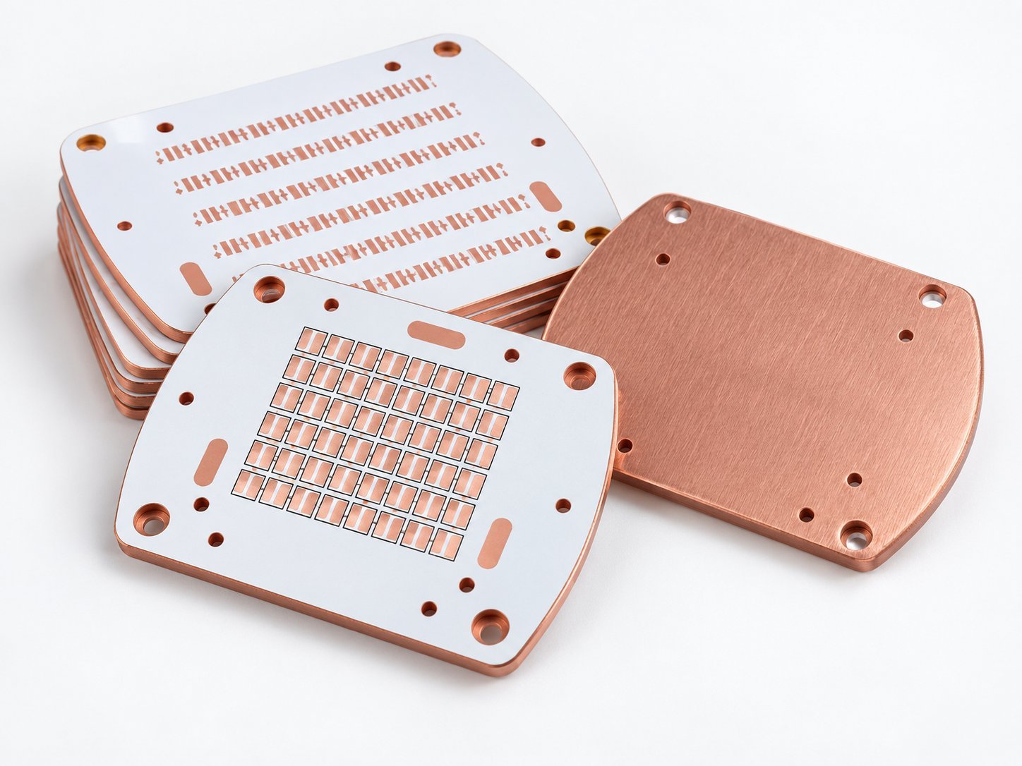
The capability list includes aluminum/copper metal-based boards. It does not establish one general base thickness, thermal conductivity or dielectric-withstand value.
On smaller screens, scroll within the table to see every column.
| Parameter | Published capability | Applies to | Review conditions |
|---|---|---|---|
| Base material | Aluminum or copper metal-based construction | Listed product family | Specify exact base grade, thickness and mechanical finish |
| Circuit copper | Per approved construction | Conductive circuit layer(s) | Specify copper independently from the metal base |
| Thermal dielectric | Per selected material system | Insulating interface | Supply grade, thickness and thermal-property requirements with test conditions |
| Electrical insulation | Drawing and material specification | Circuit-to-base and mounting interfaces | Define dielectric-withstand and clearance criteria for the application |
| Mechanical thermal interface | Drawing-defined | Mounting surface, holes and outline | Show contact area, flatness/datum needs and attachment details |
Engineering review needs the heat source and the path into the equipment.
Provide a heat-source map or identify the components and areas that drive the thermal requirement. Show the intended cooling interface, mounting method and any electrically isolated regions.
If a material property is mandatory, identify the exact measurement condition or manufacturer documentation that defines it. Copper weight, metal-base thickness and dielectric thermal conductivity are different parameters.
Some projects need both routes; keep their specifications separate.
Send layer copper, circuit geometry, current-duty and connection requirements.
View capabilitySend base/dielectric material requirements, heat-source locations and the mounting drawing.
View capabilityAttach the full fabrication package and identify which electrical, thermal and mechanical requirements are fixed.
View capabilityInclude the drawing revision and acceptance requirements. The engineering review confirms the manufacturable combination before quotation.
No. It is the confirmed finished-copper entry for rigid inner and outer layers. Metal-base material and thickness must be specified separately.
No. Supply conductor geometry, duty, allowed temperature rise, connections and cooling conditions so the complete current path can be reviewed.
The approved capability sheet does not give a universal value. Define these requirements against the selected dielectric and material documentation.
Submit the proposed full construction. The copper, insulation, holes, thermal interface and assembly requirements need to be reviewed together before a combination is accepted.