Flex PCB Assembly
Get flexible and rigid-flex circuit assemblies built around the installed shape of your product. Send the board files, component locations, stiffener details and bend requirements to review the assembly and handling route.
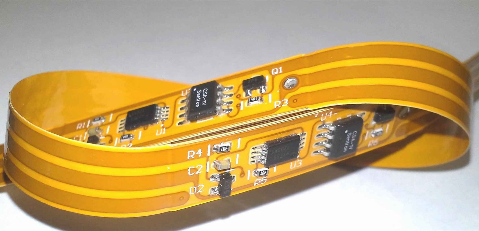
Flex PCB assembly for the way your product fits and moves
Flexible circuits connect parts of a product while accommodating limited space, a formed shape or movement. Component areas still need stable support during printing, placement and soldering, and the finished circuit must be handled around its intended bend regions.
GlobalWellPCB reviews the circuit construction and assembly requirements together. Explain the installed shape, component support and connection points so the quoted work reflects how the flex assembly will be used and delivered.
Connect the flex stackup to component placement and support.
Keep bend zones, connector access and final shape in the project brief.
Specify carriers, support and protective packaging where needed.
Agree electrical checks and any fit review for the final configuration.
Choose the work your order needs
Flexible circuits with stiffeners
Support populated areas or connectors with the specified stiffener design. Supply locations, materials and thickness so the assembly handling plan matches the drawing.
Rigid-flex assemblies
Combine rigid component regions and flexible interconnects in one assembly. Identify the board transitions, populated sides and final folding or installation sequence.
Formed and repeated-motion circuits
Distinguish a one-time installation bend from repeated movement. State the bend areas and handling limits from your design when discussing manufacturing and delivery.
How the project moves forward
- 01
Send flat and installed views
Include Gerber, BOM, CPL and drawings showing stiffeners and bend zones.
- 02
Review support and assembly sequence
Discuss fixtures, component areas, thermal exposure and the order of operations.
- 03
Approve the build and handling
Confirm the construction, any formed shape, inspection and packaging requirements.
- 04
Receive assemblies for integration
Deliver to the agreed configuration and handling conditions for your product build.
What to send for a useful quotation
| File or requirement | Details to include |
|---|---|
| PCB fabrication files | Gerber and drill data, board construction and any panel requirements. |
| Component BOM | Exact manufacturer and MPN, quantity, fitted references and approved alternatives. |
| Placement file | CPL / pick-and-place data identifying X/Y, side, rotation and reference designator. |
| Assembly drawing | Polarity, DNP positions, mechanical details and special component instructions. |
| Stiffener and bend drawing | Show support areas, keep-outs, bend zones and installed shape with dimension references. |
| Handling and fit requirements | Define carrier needs, connector access, packaging and any customer fit check. |
Include the quantity, current revision and required delivery date. If a decision is still open, identify it in your message so the review can address it.
Know what will be checked and returned
| Review area | What it covers | What to specify |
|---|---|---|
| Population and supported regions | Check components and soldering against the assembly drawing. | Identify unsupported areas and handling restrictions. |
| Bend and rigid-flex transitions | Review the construction and installed geometry against your design. | Specify the bend condition and required fit evidence. |
| Electrical and interface checks | Agree continuity or functional checks using the intended access points. | State fixtures, connectors and test conditions. |
State any unit or batch identification, packaging and inspection or test records you need with delivery. The quotation confirms the operations and evidence included.
What shapes your quotation
A useful quotation describes the complete deliverable and its supply responsibilities. Include these items in the review so you can compare like-for-like scope.
- Flexible or rigid-flex board construction and component population.
- Stiffeners, support carriers, tooling and any forming or bonding steps.
- Electrical checks, fit verification and protective delivery packaging.
The delivery plan follows file readiness, approved materials and the requested operations. Share your target date and any items already available to help review the schedule.
Frequently asked questions
Is rigid-flex the same as flex with a stiffener?
No. Rigid-flex includes electrically connected rigid and flex regions; a stiffener provides local mechanical support. The construction drawing should make the intended design clear.
Should I show the finished bend shape?
Yes. Include the installed view, bend regions and whether movement is repeated or occurs only during installation. This helps review support, assembly and packaging.
Can components be placed near a bend?
Send the layout and bend drawing for review. Suitable clearance depends on the construction and movement required; do not rely on a generic distance.
How should completed flex assemblies be packed?
Specify whether the circuit is delivered flat or formed, and identify vulnerable connectors or bend regions. Protective support and packaging are agreed with the order.
Related services for your build
Discuss your Flex PCB Assembly requirements
Send the files, quantity and deliverable you need. Add your supply responsibilities, target date and any test or documentation requirements so the review covers the complete order.