GlobalWellPCBPCB & PCBA Manufacturing
GlobalWellPCB

Selective Soldering

Request selective soldering for specified through-hole joints on a mixed-technology board. Provide the assembly drawing, underside layout and thermal restrictions to review access, tooling and acceptance.
01
Identify the jointsThrough-hole locations & drawing
02
Review the accessNozzle clearance & thermal mass
03
Agree the evidenceInspection & process records
Working with GlobalWellPCB

Target the through-hole joints within your mixed assembly

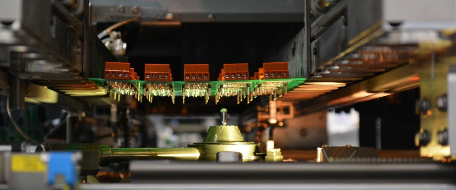
Selective soldering applies a local soldering operation to designated joints rather than treating the whole board in the same way. It can be useful when through-hole connectors and other leaded parts share the assembly with surface-mount components.

GlobalWellPCB reviews the access around each target joint, nearby components and thermal mass before defining a process route. Identify the locations and restrictions that make the operation necessary for your product.

Local requirements made explicit

Identify the joints to solder and the surrounding restrictions.

The complete board considered

Review underside SMT parts and thermal limitations.

Tooling included in the scope

Bring fixture and support needs into the quotation.

Acceptance tied to the joint type

Define the inspection and electrical checks required.

Choose the scope

Choose the work your order needs

Selected through-hole joints

Define the connectors or leaded parts requiring a local soldering step. Show their orientation, holes and accessible underside area.

Mixed SMT and leaded assemblies

Plan the selective operation within the complete assembly sequence. Include sensitive components and previously assembled areas that must be considered.

Process and fixture review

Discuss pallets, support or access solutions for constrained boards. Provide the actual geometry instead of assuming a universal nozzle clearance.

Your order from start to finish

How the project moves forward

  1. 01

    Identify the target joints

    Send assembly views, BOM and finished-hole information.

  2. 02

    Review access and thermal needs

    Assess nearby components, copper areas and support requirements.

  3. 03

    Approve the process scope

    Confirm the route, tooling and acceptance criteria.

  4. 04

    Solder and inspect

    Complete the agreed joints and board checks before release.

Prepare your enquiry

What to send for a useful quotation

File or requirementDetails to include
Board filesGerber, drill information and complete populated views.
Leaded component BOMExact MPNs, references, quantity and mechanical drawings.
Assembly instructionsOrientation, insertion and supporting-part requirements.
Order scopeQuantity, mixed-technology route and required delivery configuration.
Target-joint drawingMark selective locations, lead and hole geometry, orientation and seating.
Underside and process restrictionsShow component heights, keep-outs, thermal limits and any pallet or fixture interface.

Include the quantity, current revision and required delivery date. If a decision is still open, identify it in your message so the review can address it.

Agree the acceptance

Know what will be checked and returned

Review areaWhat it coversWhat to specify
Joint and component placementCheck the inserted parts and orientation to the drawing.Specify seating and lead-trim requirements.
Solder-joint appearanceInspect the designated joints to the agreed acceptance criteria.Name any critical locations or measurements.
Board-level checksVerify connections or product operation within the required test scope.Provide mating interfaces, procedure and limits.
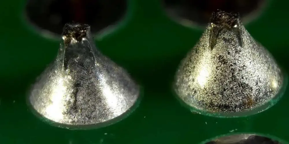
Magnified view of two solder joints on a green circuit-board surface
Solder-joint close-up. Illustrative example.

State any unit or batch identification, packaging and inspection or test records you need with delivery. The quotation confirms the operations and evidence included.

Compare the complete order

What shapes your quotation

A useful quotation describes the complete deliverable and its supply responsibilities. Include these items in the review so you can compare like-for-like scope.

  • Number and distribution of target joints and thermal mass.
  • Access complexity, support tooling and the mixed assembly sequence.
  • Inspection, electrical tests and requested process records.

The delivery plan follows file readiness, approved materials and the requested operations. Share your target date and any items already available to help review the schedule.

Answers before you order

Frequently asked questions

Is selective soldering always better than wave soldering?

The appropriate route depends on access, board population and thermal requirements. Send the assembly for comparison rather than choose from the service name alone.

What is the most useful drawing to send?

A view identifying target joints and an underside view showing nearby components, heights and keep-outs. Include exact leaded component data.

Can it be included with SMT assembly?

Yes. Request the complete mixed-technology route so printing, placement, reflow and through-hole operations are reviewed together.

Are nozzle clearances fixed for every board?

No. Access is reviewed with the equipment, joint geometry and surrounding components for the specific build.

Start your project

Discuss your Selective Soldering requirements

Send the files, quantity and deliverable you need. Add your supply responsibilities, target date and any test or documentation requirements so the review covers the complete order.

Request a quotation
Scroll to Top