PCB Stencil
Prepare the stencil needed for your SMT assembly. Send the paste layers, board or panel revision and printing requirements to discuss foil construction, frame format and aperture review.
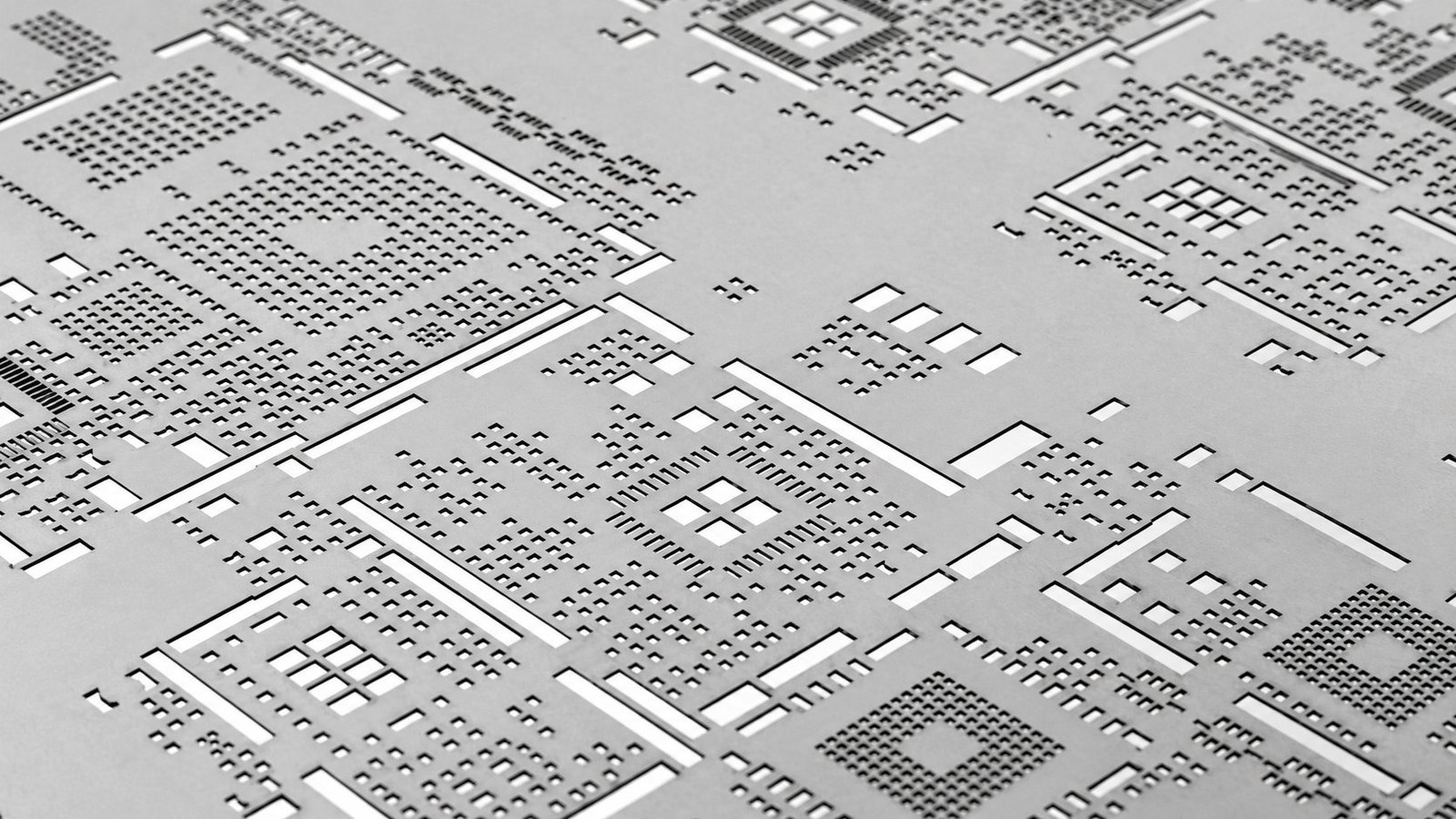
A controlled paste pattern starts with the right stencil.
A PCB stencil is the patterned foil used to deposit solder paste on surface-mount pads before component placement. Its apertures, thickness and mounting interface work together with the board, paste and printing process.
Start with the released paste layers and the assembly revision. Exposed copper, unpopulated positions and large thermal pads can need different paste treatment, so a copper layer alone does not define the stencil artwork.
Scroll horizontally to view the complete table.
| Specify | What to establish |
|---|---|
| Artwork and side | Board or panel revision, top/bottom identification, fiducials and approved paste layers. |
| Mounting format | A dedicated frame, reusable tensioning holder or defined manual fixture. |
| Foil and apertures | Local thickness, opening geometry and the critical component families. |
| Acceptance | The finished-tool checks and the printing checks required for the order. |
Compare mounting, manufacture and foil profile separately.
Framed, laser-cut and stepped describe different choices within a stencil specification. Select the relevant options together against the printing equipment and deposit requirements.
Scroll horizontally to view the complete table.
| Design choice | Common descriptions | What to compare |
|---|---|---|
| Mounting | Framed / frameless | A framed foil stays with its dedicated support. A frameless foil needs a compatible holder or fixture; it can also be used with automated equipment. |
| Aperture manufacture | Laser-cut / chemically etched / electroformed | Review the required opening geometry, wall condition and inspection evidence with the chosen manufacturing route. |
| Foil profile | Single thickness / stepped | Use one thickness where the opening families can share a process. Review local thickness changes where component groups need different deposits. |
| Surface treatment | Electropolishing / specified coating | Identify the printing or release requirement that a treatment is intended to address, together with cleaning and handling requirements. |
Record the agreed construction and any special process on the approved stencil specification. Available options and their acceptance requirements are confirmed during the project review.
Review paste volume and release geometry together.
Foil thickness changes both the volume inside an opening and the wall area that contacts the paste. Review the smallest apertures alongside larger connector, power and exposed-pad deposits before choosing a construction.
Aperture geometry
Use finished opening dimensions, shape and corner treatment. Identify fine-pitch leads, small chips and other critical openings in the paste artwork.
Local foil thickness
Evaluate the thickness at each aperture family. A step changes a local deposit requirement and also needs a defined zone and transition clearance.
Paste and process
Paste properties, aperture wall condition, alignment, support and separation affect the printed result. A geometry calculation supports the process review.
Geometric opening volume = opening area × local foil thickness. Area ratio = opening area ÷ (opening perimeter × local foil thickness).
Scroll horizontally to view the complete table.
| Rectangular opening | Foil thickness | Opening volume | Area ratio |
|---|---|---|---|
| 0.30 × 0.50 mm | 0.10 mm | 0.015 mm³ | 0.938 |
| 0.30 × 0.50 mm | 0.15 mm | 0.0225 mm³ | 0.625 |
This unchanged-opening example illustrates the tradeoff: the thicker foil holds more paste and has a lower area ratio. These are geometric values, not a prediction of transferred paste, a universal thickness recommendation or a production acceptance limit.
QFN and exposed-pad openings
Review perimeter leads and the exposed pad as distinct deposit patterns. Segmented openings can divide a large pad into controlled regions; the window layout, webs and edge margins need package-specific review. Paste coverage alone does not determine the final solder voiding result.
For package-specific background, see Texas Instruments’ QFN and SON attachment guide. Use the actual component drawing and approved process when releasing artwork.
Specify the printing interface as well as the panel.
Provide the printer model, holder drawing or fixture requirements together with the production-panel drawing. Keep these dimensions separate so the usable printing area and equipment interface can be reviewed.
Scroll horizontally to view the complete table.
| Dimension or feature | Information to send | Why it matters |
|---|---|---|
| Outer frame | Outside dimensions, frame profile and printer mounting interface. | Mechanical fit is established at the equipment interface. |
| Foil and holder | Foil dimensions, clamping or tensioning features and holder identification. | A frameless foil must match the system that supports it. |
| Usable print area | Aperture image limits, blade direction and required working clearance. | The complete pattern must fit the available printing region. |
| PCB or panel | Panel outline, rails, orientation, fiducials and side identification. | Registration and board support follow the intended production layout. |
If top and bottom patterns share one foil, submit the proposed arrangement for review. Confirm usable area, interference clearance and clear side identification before treating it as a substitute for separate stencils.
Connect the approved artwork to the first print.
Stencil preparation and release
Review the files
Identify the released paste layers, panel, printing sides, critical packages and mounting system.
Approve the specification
Confirm the manufacturing route, foil profile, apertures, dimensions and any requested finishing.
Make and check the tool
Prepare the stencil to the approved data and review the required identification, dimensions and aperture checks.
Release for the build
Keep the approved artwork and inspection requirements with the correct board revision and printing setup.
Printing sequence
Support and align
Locate and stabilize the board or panel, then align the correct stencil side using the defined registration features.
Print and separate
Use the agreed paste and printing settings. Control contact, the print stroke and separation as parts of one process.
Inspect and maintain
Check the deposit before placement. Review cleaning, handling and storage against the paste, stencil and process requirements.
Check the stencil and the printed deposit at their own stages.
Define what the order needs to demonstrate and which records are required. Tool inspection and assembly-process inspection answer different questions.
Scroll horizontally to view the complete table.
| Stage | Review focus | Agree before release |
|---|---|---|
| Finished stencil | Approved artwork, side and revision, dimensions, apertures and specified construction. | Inspection features, acceptance dimensions, identification and any required record. |
| Printed solder paste | Deposit position and the required paste characteristics before component placement. | SPI or other suitable print checks, sampling and reporting within the assembly scope. |
| After assembly | The agreed inspection or test of the populated and soldered board. | The separate assembly inspection and test scope; this does not replace tool or paste checks. |
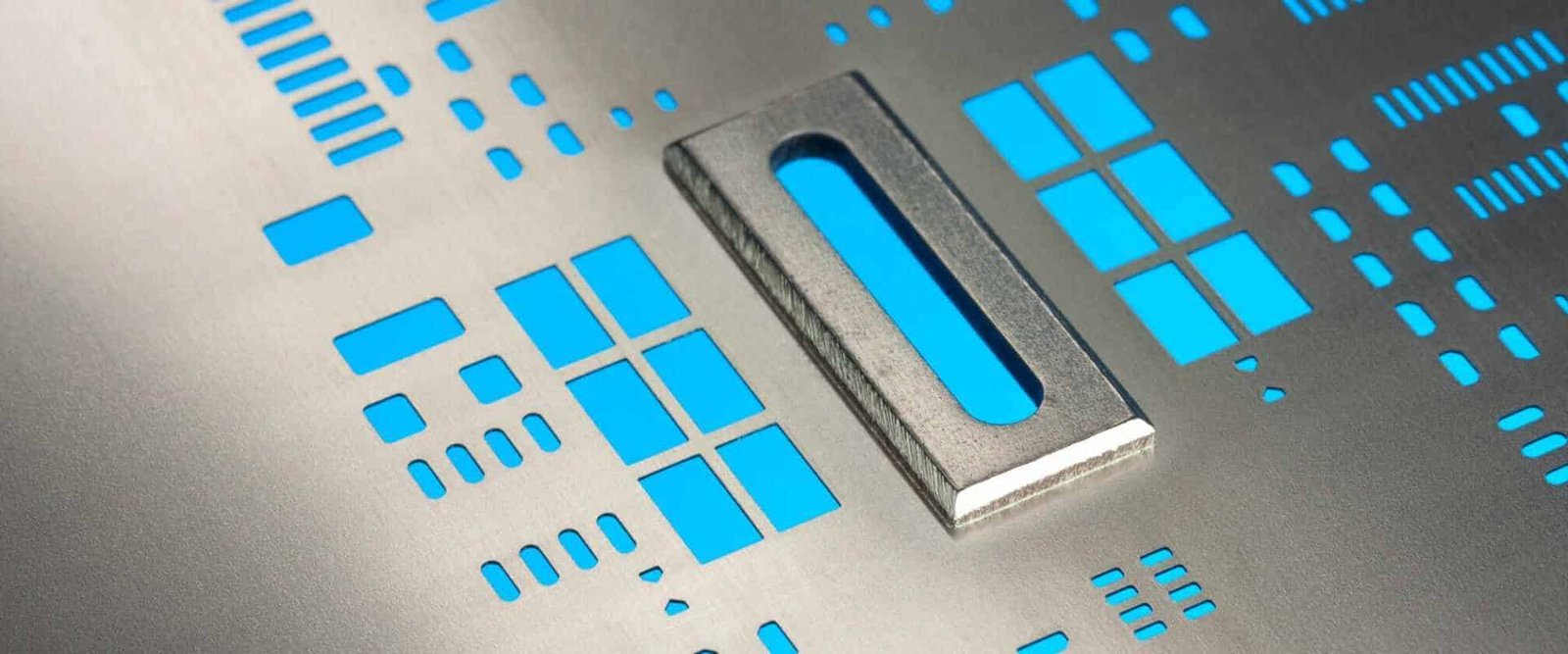
Include any traceability, packaging or inspection-report requirement in the enquiry so it can be reflected in the quotation.
Compare quotations for the same stencil deliverable.
Stencil cost follows the physical tooling and the work included. Identify the complete scope before comparing a framed tool, a reusable-holder foil or a custom construction.
Quantity and printing sides
State the number of physical stencils or foils, printing sides and any separate sets. Board quantity is a separate assembly input.
Construction and preparation
Include image size, mounting format, aperture work, local steps, surface treatment and any requested artwork optimization.
Inspection and delivery
Specify identification, records and packaging. Include destination and timing so the frame size and delivery requirements can be reviewed.
For repeat builds, identify the existing stencil and the current board revision. Reuse is reviewed against artwork, equipment compatibility and tool condition.
Send the stencil data and the decision you need help with.
You can request a stencil with an assembly order or submit a separate stencil requirement. Mark unresolved items clearly so the review addresses the actual design or printing question.
Scroll horizontally to view the complete table.
| File or requirement | What to include |
|---|---|
| Paste artwork | Released top and bottom paste layers, orientation, fiducials and board revision. |
| Panel and assembly context | Panel outline, rails and assembly drawing; identify critical packages, unpopulated positions and assembly variants. |
| Printing equipment | Printer model, frame or holder interface, usable print area and any manual-fixture drawing. |
| Stencil brief | Physical quantity, sides, foil thickness preference, local steps and requested finishing or aperture review. |
| Delivery and acceptance | Destination, target date, identification, packaging and the inspection or records required. |
If you are investigating a print issue, add photographs or inspection results tied to the same revision, the affected locations and the relevant printing conditions.
Send your stencil / assembly enquiry →PCB stencil questions before you order.
Are PCB stencils and SMT stencils the same thing?
Both terms commonly describe the patterned tooling used for solder-paste printing during surface-mount assembly. The order still needs the artwork, construction, mounting interface and printing-side identification.
Is a frameless stencil only for manual printing?
No. A frameless foil can be used with a suitable reusable tensioning system or printer setup. Specify the actual holder and equipment interface instead of inferring the printing method from the word frameless.
What if I have not chosen the foil thickness?
Send the paste artwork, critical component details and the known printing requirements. Mark thickness as open for review. It should be evaluated with the opening geometry and the complete range of deposit requirements.
Does a mixed-component board always need a step stencil?
No. First review the deposit requirements and aperture families together. Local foil thickness changes are one option to evaluate where they address a defined printing requirement.
Can the solder-mask layer be used as the paste artwork?
The solder-mask layer defines a different feature. Supply the released paste layers and confirm any requested aperture changes against the assembly revision and component requirements.
Can a stencil be reused for a new board revision?
Compare the current paste and panel data with the existing tool, then review mounting, identification and condition. A familiar board name alone is not enough to establish reuse.
Can stencil supply be included with PCB assembly?
Include stencil supply and printing requirements in the assembly enquiry. The quotation identifies the tooling, assembly operations and inspection or test work included.
Related services for your build
Discuss your PCB Stencil requirements
Send the files, quantity and deliverable you need. Add your supply responsibilities, target date and any test or documentation requirements so the review covers the complete order.