Microsection Analysis
Examine selected internal features of a PCB or assembly with a controlled cross-section. Define the question, sample location, preparation and acceptance evidence before cutting.
See the internal feature that surface inspection cannot.
Microsection analysis exposes a selected plane inside a specimen for microscopic examination. It is a destructive technique: material is removed during sectioning and preparation, so the sampled piece cannot be treated as an unchanged production board afterward. [S33]
For your GlobalWellPCB project, start with the question to answer—such as a plated-hole feature, a layer interface or a selected assembly joint. Define the sample source and plane before preparation, because the observed section only represents the material actually exposed.
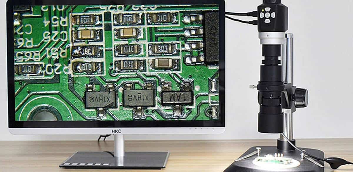
Select the feature before selecting the sample.
The observations below are possible investigation targets. The available resolution, preparation route and acceptance criteria must be confirmed for the actual specimen.
Scroll the table horizontally to see all columns.
| Review area | What to evaluate | What to agree |
|---|---|---|
| Plated through-holes | Selected hole-wall plating, copper interfaces and local interconnection features. | Identify hole type, intended section plane and measurement locations. [S20] |
| Microvias and buried structures | Selected via geometry and internal interfaces at the exposed plane. | Confirm that the preparation can reach the feature of interest. [S34] |
| Layer construction | Visible copper/dielectric relationships and localized layer dimensions. | Map the sample to the relevant stackup and region. [S33] |
| Assembly joints | Selected soldered interfaces or internal joint features after assembly. | Identify the component reference and joint location before destructive work. [S33] |
| Condition comparison | As-received material versus a separately defined conditioned sample. | Specify any thermal or mechanical conditioning; do not imply it occurred automatically. |
| Failure investigation | A targeted observation that may support or challenge a proposed failure mechanism. | Preserve the history and distinguish observed evidence from root-cause inference. |
Tell us which features need inspection, your sampling requirements and the reports you need. We will confirm these details in your quotation.
From a clear requirement to a documented decision.
- 01
Define the investigation
Provide the drawing, specimen identity, failure history and precise question. Agree whether a coupon or a sacrificial product sample is appropriate.
- 02
- 03
Inspect and record
Capture useful overview and detail views, with scale and identified locations. Take the measurements required by the approved method.
- 04
Interpret within the scope
Compare observations with agreed criteria. Identify preparation concerns, inconclusive features and any additional sampling needed before drawing a wider conclusion.
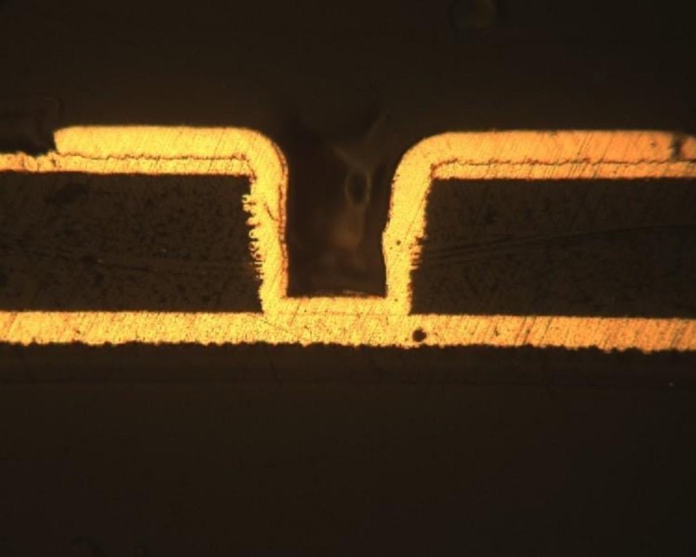
Keep the image tied to the specimen.
Ask for more than a magnified picture. The report should explain where the section came from, how it was prepared and what the observations can legitimately support.
- Sample provenance
- Part/revision, lot or panel, coupon or board identity, and specimen condition on receipt.
- Location map
- Feature reference, cutting orientation and a map linking the examined plane to the original item.
- Image and measurement
- Overview/detail images, calibrated scale, stated measurement locations and relevant observations.
- Interpretation
- Acceptance basis, pass/fail where appropriate, preparation limitations and any qualified investigation conclusions.
One polished plane is not the whole board.
A local section can miss a defect outside its plane. Preparation artifacts can also complicate interpretation, so an unusual feature may need another section or a complementary method. Do not turn an isolated observation into a claim that all boards or every interconnect have been verified. [S20] [S34]
Microsection Analysis FAQs
Find answers about inspection methods, reports and approvals before placing your order.
Is microsection analysis destructive?
Yes. It requires removal of material to expose the internal plane. Authorize the sample consumption and decide whether to use a coupon or a sacrificial product specimen. [S33]
Can a coupon replace a section from the product?
It can represent specified fabrication structures when its relationship to the board is established. A product-specific failure at a local feature may require a section from that actual region.
Does every cross-section include a thermal stress test?
No. Conditioning and sectioning are separate parts of the plan. State whether specimens are examined as received, after a defined exposure or as a comparison set.
Can a section alone prove the root cause of a failure?
Not always. It provides physical evidence from the exposed plane. Combine that evidence with electrical results, process history and other observations before assigning a root cause.
What thickness limits should be used?
Use the applicable drawing, product requirements and agreed method. Do not apply one advertised copper or dielectric limit to every hole type, construction or product class.
Connect the next part of your quality plan.
Technical references
- [S20]Struers — Metallography of microelectronics
- [S25]Nordson — Automated X-ray Inspection Product Portfolio (PDF)
- [S33]Leica Microsystems — Cross-section quality control of electronics
- [S34]Leica Microsystems — Cross-section analysis for electronics
Explore the inspection and testing references below. Include the applicable standards, acceptance criteria and required records with your enquiry so we can confirm the inspection plan for your board.