Metal Core PCB
Manufacturing
A clearer path from heat source to heat sink.
Plan your aluminum- or copper-base PCB with the complete thermal assembly in mind. Bring your stackup, insulation requirements and mounting details to GlobalWellPCB for a project-specific manufacturing review.
Material selection, build limits and inspection scope are confirmed against your design.

What is a metal core PCB?
A metal core PCB (MCPCB) incorporates a metal base or core into its construction to support heat spreading.
In a conventional insulated metal substrate (IMS), copper circuitry sits above a thermally conductive, electrically insulating dielectric bonded to an aluminum or copper plate. In this common arrangement, the metal is the backing layer—not necessarily a central layer.
Three materials. Three different jobs.
The copper routes current. The dielectric separates the circuit electrically from the base. The metal spreads heat toward the cooling structure. Specify each part of the construction, rather than one “PCB conductivity” number.
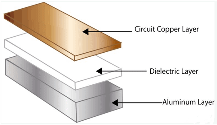
Start with the heat source
Identify the component thermal pad, dissipated heat and acceptable temperature. Do not treat total electrical input power as heat without checking the operating losses.
Define the insulation boundary
Identify which nets must remain isolated from the metal plate, mounting hardware and enclosure. Include any intentional base-to-ground connection.
Finish the cooling path
Include the mating surface, thermal interface and heat sink or housing in the project review. A board specification alone does not define the finished thermal system.
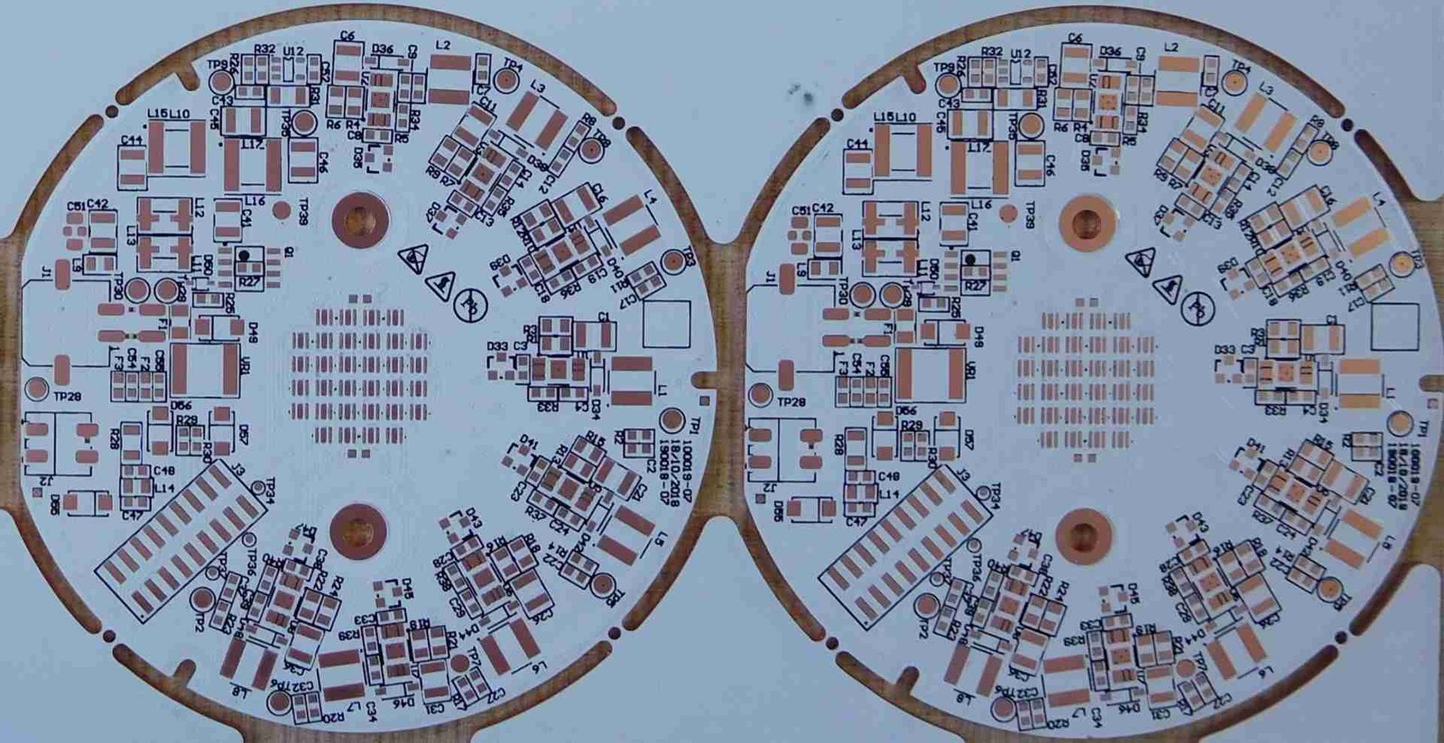
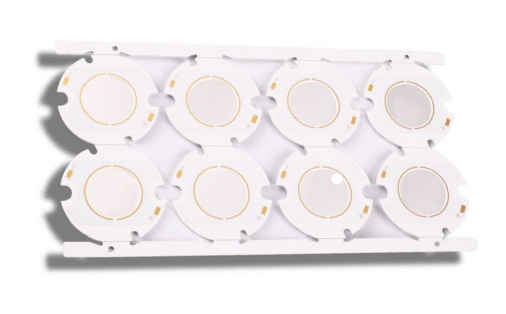
Aluminum or copper? Choose around the complete build.
Copper has higher thermal conductivity and density than aluminum. That does not make every copper-base board the better assembly: dielectric, geometry and cooling interfaces remain part of the decision.
A lighter starting point
Consider aluminum when board mass and a cost-conscious construction are important. Name the alloy and temper instead of assuming all aluminum plates have the same properties.
- Review first
- Plate thickness, stiffness, mounting holes and heat-sink contact.
- Material note
- Match the alloy to the mechanical and thermal requirements.
- Quote input
- Approved grade, finish, dimensions and alternatives.
Prioritize heat spreading
Consider copper when the design benefits from its higher conductivity, while reviewing the added mass. Quote the actual grade, machining and finish rather than applying a fixed cost multiplier.
- Review first
- Concentrated heat sources, base thickness and mounting loads.
- Material note
- A copper base does not automatically mean direct thermal path construction.
- Quote input
- Surface protection and any intentional electrical connection.
Keep conductor copper separate. “Copper-base PCB” describes the metal plate; “heavy copper PCB” describes circuit conductor thickness. Specify both independently when the design needs both.
Choose the architecture before freezing the layout.
Layer count alone does not describe an MCPCB.
Draw the copper layers, dielectric boundaries, metal plate and interconnects. Make clear whether additional routing is above the base or on both sides of a central metal core.
Special constructions need a separate review.
Multilayer, insulated through-core connections and exposed-base attachment areas should be reviewed explicitly. They are not implied by a standard aluminum- or copper-base enquiry.
- 01
Single-circuit-layer IMS
A copper circuit, dielectric and metal backing provide a straightforward construction to evaluate for surface-mounted power or lighting layouts.
- 02
Two-layer or multilayer IMS
Thermally conductive bonding systems can support additional circuit layers. Review routing, interlayer vias, insulation and the longer heat path as one stackup.
- 03
Selective direct thermal path
A designed exposed-base area or copper pedestal can bypass dielectric locally. This changes the electrical isolation at that pad; verify device compatibility and the system insulation strategy.
Compare dielectric thickness—not conductivity alone.
A thinner layer of the same dielectric can have lower through-thickness thermal impedance. Select it together with the required electrical insulation and construction tolerances.
| Dielectric example | Thickness | Dielectric conductivity | Area-normalized thermal impedance |
|---|---|---|---|
| TCLAD HT | 75 µm | 2.2 W/(m·K) | 0.32 °C·cm²/W |
| TCLAD HT | 100 µm | 2.2 W/(m·K) | 0.49 °C·cm²/W |
| TCLAD HT | 150 µm | 2.2 W/(m·K) | 0.71 °C·cm²/W |
Scroll the table horizontally on small screens. Preserve the test method and units when comparing supplier data.
Check the measurement basis
The HT data sheet separately lists product conductivity and dielectric conductivity using different methods. The table above uses its dielectric value and ASTM D5470 impedance data.
Do not interchange units
W/(m·K) describes material conductivity. °C·cm²/W is area-normalized impedance. K/W describes thermal resistance for a defined geometry. They answer different questions.
Retain the electrical requirement
Lowering dielectric thickness is not a standalone optimization. Review the working voltage, insulation boundary and qualification requirements before selecting a thinner grade.
Explore one dielectric layer.
This idealized slab model isolates the effect of thickness, conductivity and a defined heat-flow area. It is useful for comparing assumptions—not for predicting a finished board’s junction temperature.
ΔT = P × R
Steady-state, one-dimensional conduction; constant properties and uniform area. With t in µm and A in mm², the conversion factors cancel, giving R in K/W.
It excludes spreading, solder, contacts, metal-base resistance, interface material and cooling. Do not substitute the whole board area for an unverified heat-flow area.
Dielectric-only thermal estimate
Illustrative inputs. No manufacturing range or material recommendation is implied.
The idealized calculation does not reproduce a supplier’s complete test fixture or measured data.
Metal core PCB manufacturing requirements
Put the electrical, thermal and mechanical requirements in one controlled specification. Use this list to prepare the enquiry; project-specific limits require written confirmation.
| Specification | Include with your enquiry | Resolve before release |
|---|---|---|
| Metal base | Aluminum or copper grade, temper, thickness and finish. | Approved stock, dimensional tolerances and alternatives. |
| Dielectric | Named material or performance target; thickness and thermal data basis. | Insulation needs, controlled data sheet and approved substitution rules. |
| Circuit copper & layers | Copper requirements by layer, stackup and critical conductors. | Finished thickness, line/space rules and interconnect structure. |
| Holes & metal isolation | Hole types, diameters, slots, threads and net connections. | Which features connect to the base and which require insulation. |
| Mechanical interface | Outline, flatness, mounting faces and heat-sink drawing. | Machining, edge condition, contact surface and panel format. |
| Finish & assembly | Solder mask, pad finish, component package and assembly requirements. | Compatibility, inspection access and process-validation needs. |
| Operating conditions | Device losses, duty cycle, voltage, ambient and cooling arrangement. | Relevant load cases, temperature limits and validation ownership. |
| Acceptance & delivery | Standards/revisions, tests, reports, quantity and requested date. | Acceptance criteria, sampling, documentation and agreed schedule. |
Attach the fabrication drawing and identify its revision. Keep the quote, purchase order and design files consistent.
Resolve the details at the metal interface.
IMS imaging and wet processing share some methods with FR-4, but hole formation, finishing, flatness and singulation need construction-specific review.
Copper to edges and fasteners
Mark keep-outs at routed edges, slots and screw heads. Ask for process-specific spacing and any additional electrical clearance; do not copy a single generic minimum.
Hole and via isolation
Separate mounting holes, interlayer connections and intentional base connections. Review any plated feature that approaches or crosses the conductive metal plate.
Circuit copper and small features
Request routing rules for the chosen copper and process. Identify fine-pitch pads, narrow current paths and required minimum finished copper.
Flatness and mounting contact
State the mating-surface requirement and allowable board bow. Define interface material, contact coverage and assembly instructions together.
Singulation and edge condition
Discuss routing, scoring or tooling against the outline and volume. Specify burr direction, edge finishing and protection of the mounting surface.
Assembly and verification
Include soldering-profile validation and thermal-pad inspection in the assembly plan. Agree any voiding or solder-coverage criteria rather than assuming one universal limit.
Review the contact you cannot see after mounting.
Ask the mechanical and thermal teams to define the interface material, mounting sequence and contact condition. Include these assumptions in prototype validation.
For a bottom-cooled device, TI’s thermal model includes separate PCB, interface-material and heat-sink contributions. Optimizing only the base metal leaves the other contributors unchanged.
Do not turn a breakdown-voltage figure into a working-voltage claim.
Supplier data can report withstand voltage and breakdown voltage as distinct tests. Neither, by itself, specifies the safe operating voltage of the assembled product.
State the actual insulation boundary, operating conditions and required verification. Agree test connections, voltage waveform, duration and acceptance criteria before ordering.
From high-brightness lighting to power stages.
Use the application to define the heat load and installation conditions—not to assume a standard stackup or a universal power rating.
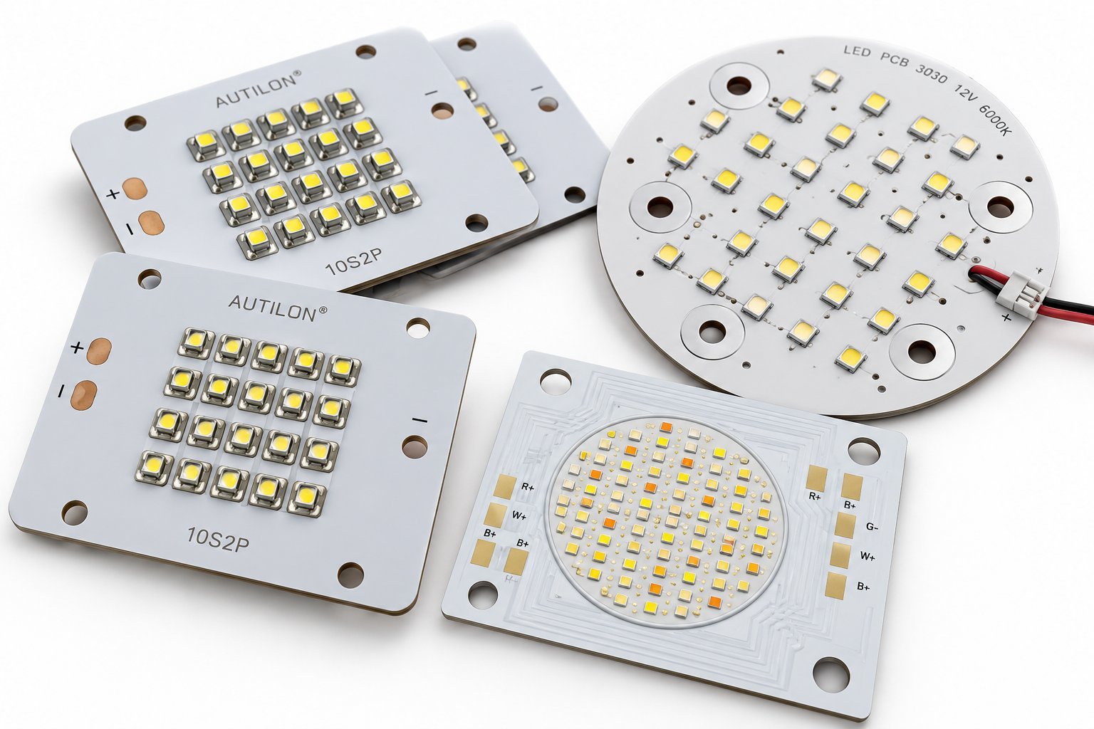
LED lighting modules
MCPCB-based lighting is documented in Lumileds’ CoB products. Review the LED thermal interface, mounting and heat sink as one assembly.
Motor-drive power stages
TI’s TIDA-00915 uses IMS for its inverter stage and separate FR-4 boards for control and isolation. Power and control need not share one substrate.
Power conversion
Consider a metal-backed construction where heat removal from the switching devices is a priority. Bring device losses and the enclosure constraints.
Custom thermal assemblies
For a board that mates to a housing or cold plate, provide the mechanical model and operating conditions so the interface can be reviewed.
Agree the evidence before the first build.
Define what fabrication acceptance must demonstrate, and what must be validated on the assembled product.
- 01 / Inputs
Review the design
Supply the files, stackup, operating conditions and mating-surface requirements.
- 02 / Agreement
Approve the construction
Resolve materials, geometry changes, insulation details and quotation scope.
- 03 / Evidence
Define inspection
Specify the measurement locations, tests, sampling and reports you need.
- 04 / Release
Validate the assembly
Check representative load cases and control later design or material changes.
Separate these acceptance questions.
- Does the board match the drawing?
- Agree dimensional checks, layer and material evidence, critical-feature inspection and required electrical testing.
- Is the intended insulation intact?
- Specify the circuit-to-base proof test separately from continuity testing, including the required final-board or panel test stage.
- Does the product meet its thermal limit?
- Define the load, ambient, cooling, measurement method and pass/fail criterion on the assembled product—not just the bare board.
Testing, reports and any qualification work must be agreed in the quotation. No certification or inspection coverage is implied by an image or an example material.
Metal core PCB questions, answered.
Key distinctions for engineering notes and sourcing conversations.
Is an aluminum PCB the same as a metal core PCB?
An aluminum-base PCB is one type of MCPCB. Conventional insulated metal substrates can also use copper. The metal name describes the base, not the circuit copper thickness.
Is a copper-base PCB the same as a heavy copper PCB?
No. A copper base is the backing plate. Heavy copper describes thicker circuit conductors. Specify these separately; choosing a copper base does not establish a current rating.
Does an MCPCB eliminate the need for a heat sink?
Not necessarily. Heat must still leave the board through the enclosure, a heat sink, airflow or another cooling path. TI’s IMS inverter and Lumileds’ MCPCB lighting examples both include heat sinks.
Does a higher dielectric conductivity always mean a cooler board?
Not by itself. Thickness, heat-flow area, interfaces and the rest of the assembly matter. Compare data measured on a consistent basis, then validate the complete design.
Can a metal core PCB have two or more copper layers?
Yes, specialized multilayer IMS constructions exist. Define the layer arrangement and interconnections explicitly; two circuit layers above a base are not the same layout as circuits on both faces of a metal core.
Can a plated hole pass through the metal base?
Only with an intentionally engineered connection or isolation structure. Do not assume an ordinary plated barrel remains isolated from conductive base metal. Show the required net and cross-section in the drawing.
Is direct thermal path construction standard on every copper-base PCB?
No. Selective dielectric removal or a pedestal is a separate construction choice. A pad connected directly to the base does not retain the dielectric isolation that was removed; review the device pad potential and system insulation design.
Is dielectric breakdown voltage the safe working voltage?
No. Breakdown and withstand values refer to particular tests, not a blanket continuous-use voltage for the finished assembly. Define working voltage, insulation requirements, clearances and the agreed verification conditions separately.
What determines metal core PCB pricing?
Ask for a quote against one controlled revision. Include the metal grade, dielectric, copper layers, finished dimensions, machining, surface finish, quantity and inspection scope. Agree material alternatives and timing before release.
Which files should I send for an MCPCB quotation?
Prepare circuit and drill data, a fabrication drawing, stackup, metal-base requirements and quantities. Include the heat-sink interface and operating conditions. For assembly, add the BOM and component-placement data.
Technical references & scope
Explore the manufacturer documents below when comparing metal-core materials. Confirm the selected grade, construction and inspection requirements with us before ordering.
- TCLAD — Insulated Metal SubstrateConstruction: copper circuitry, insulating dielectric and aluminum or copper base.
- TCLAD — Thermal Clad: Tools for an Optimal DesignRev. 2021-DG02-010. Mechanical fabrication, specialized interconnects and proof testing. Supplier-specific limits are not adopted.
- TCLAD — HT Dielectric technical data sheetRev. 2023-D02-016. Dielectric conductivity and thickness-specific thermal impedance, with stated test methods.
- Ventec — VT-4B5 SP data sheetSelective dielectric technology; distinct withstand and breakdown tests. Typical values are not application ratings.
- Texas Instruments — Thermal Comparison of FR-4 and IMS PCB for GaN InverterTIDA030, June 2019. The thermal path includes the device, PCB, interface material and heat sink.
- Texas Instruments — TIDA-00915 reference designAn IMS power stage with separate FR-4 control and isolation boards. An external reference, not a GlobalWellPCB project.
- Lumileds — LUXEON CoB Core Range application exampleA documented MCPCB lighting application used with a heat sink. No product availability or performance claim is adopted.
- TANAKA — Bonding-wire material propertiesReference physical properties of copper and aluminum; board alloys and laminates require their own data.
- TCLAD — Thermal Clad Dielectric MaterialsDielectric families, thickness options and application-dependent thermal performance.
- Ventec — tec-thermal / Thermal Management & IMSThermally conductive dielectric systems, resin-coated foil and film for multilayer constructions.
- TCLAD — Design ToolsIMS design considerations including etching, holes, finishing, flatness and singulation.
Check the exact material datasheet and test conditions when comparing supplier values. Use the construction and performance requirements approved for your board.