Taconic PCB Manufacturing
Build low-loss RF and microwave boards around the exact Taconic / AGC laminate your design requires. We review material grade, stackup, copper, impedance targets and fabrication details together before production.
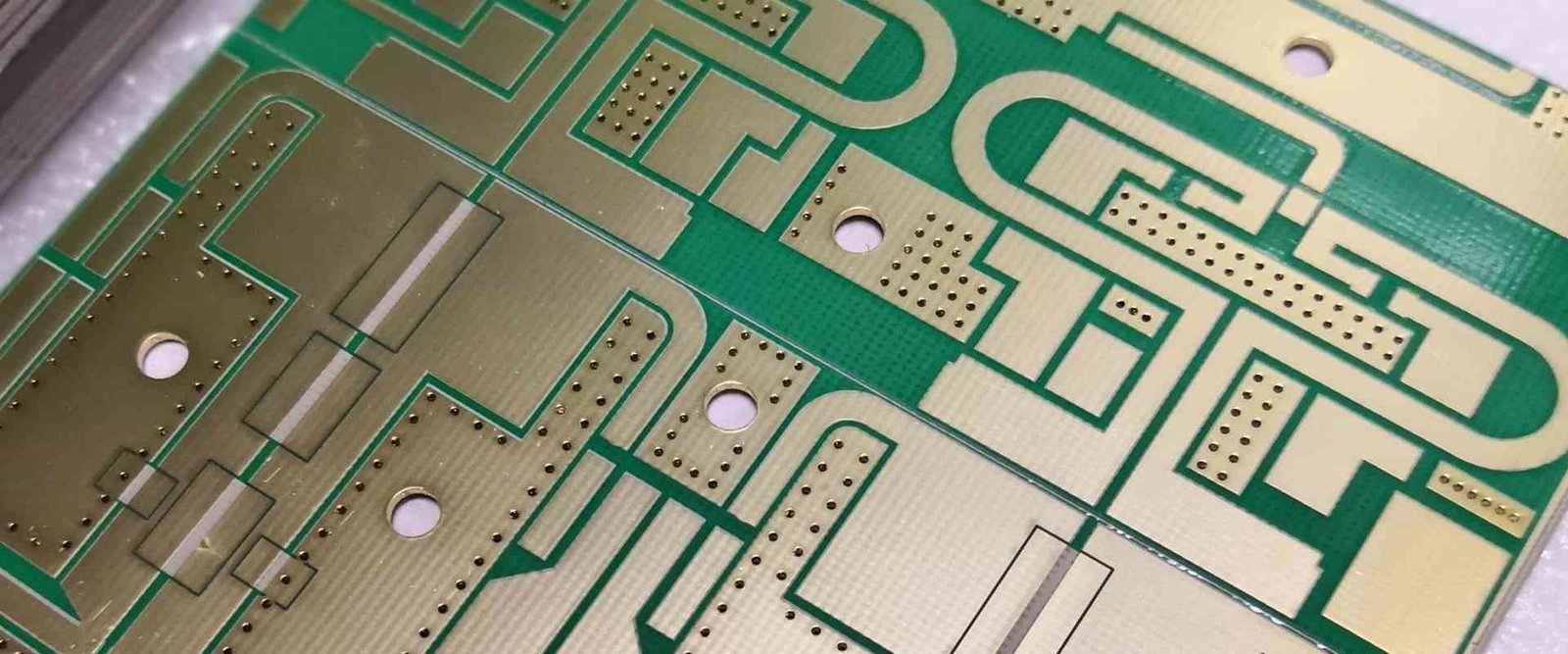
A High-Frequency PCB Built Around a Defined RF Laminate.
“Taconic PCB” generally refers to a printed circuit board using one of the high-frequency laminate families historically associated with Taconic Advanced Dielectric Division and now offered within AGC Multi Material’s RF material portfolio.
These materials are selected when a design needs more predictable dielectric behavior, lower transmission loss, tighter RF performance, specific thermal properties or a particular dielectric constant that standard FR-4 cannot provide consistently enough for the application.
Material name alone is not a complete specification. A production-ready RF board also depends on laminate thickness, copper foil type and roughness, bond-ply selection, finished copper, surface finish, controlled impedance geometry and the fabricator’s qualified process.
Choose the Grade by Electrical and Thermal Requirements.
Representative published values help narrow the choice. Final selection should use the current manufacturer datasheet and your actual stackup.
| Material | Published Description | Dk (see conditions) | Df @ 10 GHz | Thermal Conductivity | Design Fit |
|---|---|---|---|---|---|
| TLY-5A | Very low Dk base material | 2.17 ± 0.02 | 0.0009 | 0.22 W/m·K | Low-Dk antennas, 77 GHz radar and mmWave structures where very low loss matters. |
| TLX-8 | High volume antenna material | 2.55 ± 0.04 | 0.0018 | 0.19 W/m·K | Commercial antenna and microwave circuits needing PTFE-glass construction. |
| TSM-DS3 | Dimensionally stable low loss laminate | 3.00 ± 0.05 | 0.0014 | 0.65 W/m·K | Low-loss RF boards where dimensional stability is a primary design concern. |
| TLC-32 | Low cost RF laminate | 3.20 ± 0.05 | 0.0030 | 0.24 W/m·K | Cost-sensitive RF designs that still require a defined microwave laminate. |
| RF-35TC | Thermally conductive low loss laminate | 3.50 ± 0.05 | 0.0020 | 0.92 W/m·K | Power amplifiers, filters and antennas where heat spreading and RF loss both matter. |
| TLF-35A | Low cost PA base material | 3.50 ± 0.05 | 0.0026 | 0.37 W/m·K | Commercial microwave, radio-frequency and power-amplifier applications. |
| RF-60TC | High Dk, high thermal conductivity material | 6.15 ± 0.15 | 0.0020 | 1.05 W/m·K | Compact high-Dk RF structures with meaningful thermal requirements. |
| RF-10 | Low loss, high Dk material | 10.2 ± 0.3 | 0.0025 | 0.85 W/m·K | High-Dk microwave circuits, compact resonant structures and specialized RF designs. |
Published values above are taken from AGC Multi Material product tables / solution pages and are intended for early material screening. Test method, frequency, laminate thickness and copper option affect design use. Always verify the current datasheet before release.
Source: AGC Solutions Guide, June 2026, page 3. Dk is at 10 GHz except TLF-35A, whose marked value uses modified stripline IPC-TM-650 2.5.5.5.1 at 1.9 GHz (guide note 3, page 5). Df is at 10 GHz. Thermal conductivity values are typical material-guide values. Source checked 14 October 2026.
Material Performance That Supports RF Repeatability.
The value is not the brand name itself. It is the ability to select a laminate with a defined electrical and thermal profile for the circuit.
Low Dissipation Factor
Lower dielectric loss helps protect insertion-loss budgets in microwave transmission lines, filters, feed networks and antenna structures.
Defined Dielectric Properties
Tighter Dk control gives the stackup engineer a better foundation for transmission-line geometry, phase control and antenna tuning.
Application-Specific Heat Performance
Thermally conductive grades such as RF-35TC and RF-60TC support RF circuits where dielectric loss and local heat must be managed together.
Wide Dk Selection
Low-Dk, mid-Dk and high-Dk families let designers trade physical size, field distribution, bandwidth, loss and thermal behavior against project priorities.
Where Taconic RF Laminates Are Commonly Considered.
AGC positions its RF/microwave materials for wireless, automotive, avionics/aerospace and other high-frequency markets. The right grade still depends on frequency, loss target, power level, environmental requirements and fabrication route.
Base-Station & RF Antennas
Controlled Dk and low loss support feed networks, patch antennas, arrays and other frequency-sensitive structures.
Radar Sensors
Very low-loss grades are used for high-frequency radar structures, including applications around the 77 GHz automotive band.
Power Amplifiers
PA boards can require a balanced choice across dielectric loss, heat spreading, copper adhesion and mechanical reliability.
Filters & Couplers
Resonant and coupled structures benefit from predictable dielectric behavior and controlled laminate thickness.
Satellite Communications
Low-loss materials support feed networks, LNB/LNA functions and other RF front-end circuitry used in satellite systems.
Avionics & Aerospace RF
High-reliability microwave materials are considered for radar, communication and other demanding RF assemblies.
Treat the RF Layer, Copper and Bonding System as One Stackup.
A Taconic laminate can be used in simple double-sided RF boards, multilayer PTFE constructions or hybrid RF/digital stackups. The correct build depends on the selected material family and its processing guidance.
Dk similarity is not enough for automatic substitution. Thickness, filler system, copper option and process window also matter.
Provide target impedance, reference plane, line type, finished copper and relevant tolerance so geometry can be reviewed before fabrication.
Bond ply or prepreg selection must match the chosen construction and the manufacturer’s processing guidance.
At high frequency, conductor roughness can become a meaningful part of insertion loss. Specify copper requirements when the loss budget is tight.
RF Laminate Processing Needs Grade-Specific Discipline.
PTFE-based laminates should not be treated as generic FR-4. Drilling, surface preparation, bonding and thermal cycles must align with the selected material system.
Material Availability
Confirm exact grade, dielectric thickness and copper option before final lead time and commercial commitment.
Stackup Review
Align laminate, bond ply, finished thickness, impedance references, via architecture and surface finish.
Process Control
Use material-appropriate drilling, surface preparation, plating and lamination controls rather than a generic FR-4 recipe.
Acceptance Data
Define electrical test, impedance coupon, dimensional and documentation requirements before the production release.
Taconic vs Conventional FR-4.
Taconic is not automatically “better.” It is justified when the electrical, thermal or dimensional requirements of the RF circuit exceed what a conventional FR-4 stackup can deliver with acceptable margin.
For lower-frequency or less loss-sensitive designs, FR-4 may remain the more practical and economical choice. Material selection should come from the loss budget and circuit model, not brand preference.
Start with the Stackup, Not Just the Board Outline.
For RF work, quotation quality depends on complete material and electrical requirements. We structure the review around those details first.
Share the RF Requirements
Send Gerber or ODB++, stackup, material grade, copper requirements, board thickness, quantity and target frequency band.
Review Material & Stackup
Check laminate choice, thickness, bonding system, impedance geometry, via requirements and surface finish together.
Confirm Process & Quote
Resolve material availability, controlled features and inspection scope before the production quotation is finalized.
Build, Verify & Deliver
Fabricate to the released stackup and complete the agreed electrical, dimensional and documentation checks.
Send the Details That Control RF Performance.
A useful Taconic PCB quote needs more than layer count and board size. Include the electrical and material inputs that define the stackup.
Gerber or ODB++, NC drill, fabrication drawing and quantity.
Exact Taconic / AGC grade, dielectric thickness, copper weight or foil requirement and any approved alternatives.
Controlled impedance values, target frequency band, critical line types and any insertion-loss or phase requirements.
IPC class, test scope, impedance coupon requirements, reports and applicable acceptance criteria.
Recommended Taconic PCB Checklist
- Exact material grade and revision are identified.
- Layer stackup and dielectric thicknesses are defined.
- Finished copper and copper foil requirements are stated.
- Controlled-impedance lines include target values and tolerances.
- Hybrid constructions identify every dielectric and bond layer.
- Surface finish, via treatment and finished board thickness are specified.
- Any RF-specific acceptance data is agreed before production.
Taconic PCB FAQ.
What is a Taconic PCB?
A Taconic PCB is a printed circuit board built with a high-frequency laminate from the Taconic product family now integrated into AGC Multi Material’s RF material portfolio. These laminates are commonly selected for RF, microwave, antenna, radar and other loss-sensitive applications.
Which Taconic material has the lowest published Df in this table?
TLY-5A is published by AGC with a dissipation factor of 0.0009 and a dielectric constant of 2.17 ± 0.02. It is positioned as a very-low-Dk material and is cited by AGC for applications including 77 GHz automotive radar and mmWave antennas.
Can Taconic materials be used in multilayer or hybrid PCB stackups?
Yes, depending on the exact material family and construction. Multilayer and mixed-dielectric builds require the bonding system, lamination cycle and layer architecture to be reviewed against the selected material’s current processing guidance.
Is Taconic a direct replacement for Rogers laminate?
Not automatically. Different brands may offer grades with similar nominal Dk or Df, but copper options, thicknesses, thermal behavior, processing and qualification history can differ. A substitution should be rechecked in the stackup and RF design before production.
What files should I provide for a Taconic PCB quote?
Provide Gerber or ODB++, drill files, fabrication drawing, stackup, exact laminate grade, dielectric thicknesses, copper requirements, controlled-impedance targets, surface finish, board thickness, quantity and any required test or reporting scope.
Why does copper foil matter on a high-frequency board?
At microwave and millimeter-wave frequencies, conductor surface roughness can contribute to transmission loss. When the loss budget is tight, the specified copper foil and the impedance/loss model should use consistent assumptions.