Isola PCB Manufacturing
Material-specific PCB fabrication for high-reliability, high-speed digital and RF designs using Isola laminate and prepreg systems. Review the grade, stackup, copper profile and controlled features as one manufacturing specification.
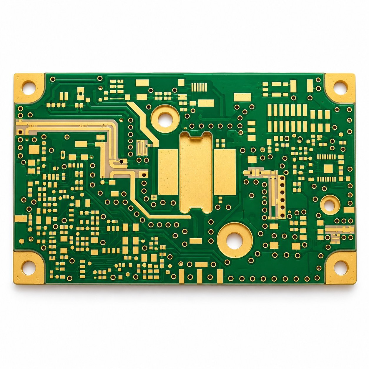
An Isola PCB Is a Material Choice — Not a Single Board Type.
Isola supplies multiple laminate and prepreg systems for different electrical and reliability targets. A multilayer server board, an automotive radar PCB and a high-reliability industrial controller may all be described as “Isola PCB,” while requiring very different resin systems and stackups.
The practical starting point is the design requirement: thermal robustness, lower insertion loss, stable dielectric behavior, high-speed digital channels, RF/microwave performance, HDI processing or a combination of these.
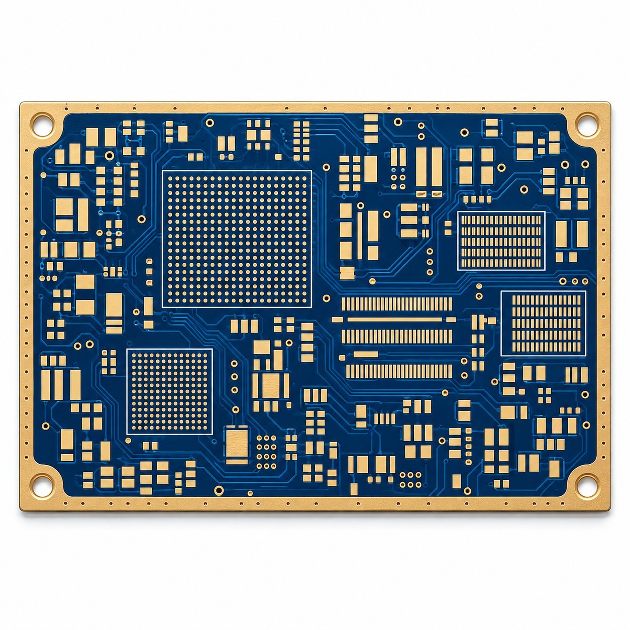
Choose the Material by the Design Driver.
Avoid selecting a laminate only by brand recognition or Tg. Loss, dielectric behavior, copper roughness and the actual stackup can be equally important.
Thermal & Process Robustness
For designs where lead-free assembly, CAF resistance, sequential lamination or broad manufacturing familiarity are key drivers.
- Typical family: 370HR
- Focus: thermal reliability and robust multilayer processing
High-Speed Digital Channels
For multilayer designs where insertion-loss budget and channel performance require a step beyond conventional high-Tg FR-4.
- Typical families: FR408HR, I-Speed
- Focus: lower loss while retaining FR-4-style processing
Advanced HSD & RF/Microwave
For very high-speed digital, RF/microwave and millimeter-wave designs requiring tighter control of dielectric and conductor-related loss.
- Typical families: I-Tera MT40, Tachyon 100G, Astra MT77
- Focus: low Df, stable electrical performance and suitable copper/glass constructions
A Practical Material Comparison.
Use this as an initial discussion guide. Final design values must come from the current Isola datasheet and the actual laminate/prepreg construction.
| Material | Positioning | Tg | Td | Dk @ 10 GHz* | Df @ 10 GHz* | Typical Design Direction |
|---|---|---|---|---|---|---|
| 370HR | High-reliability epoxy laminate / prepreg | 180°C | 340°C | 3.92 | 0.025 | Reliable multilayer PCBs, sequential lamination, broad lead-free applications |
| FR408HR | Lead-free, mid-loss laminate / prepreg | 190°C | 360°C | 3.65 | 0.0095 | High-performance multilayers needing lower loss than conventional FR-4 |
| I-Speed® | Low-loss epoxy laminate / prepreg | 180°C | 360°C | 3.63 | 0.0060 | High-speed digital channels and signal-integrity-driven multilayers |
| I-Tera® MT40 | Very-low-loss laminate / prepreg | 215°C | 360°C | 3.45 | 0.0031 | High-speed digital and RF/microwave multilayer or hybrid designs |
| Tachyon® 100G | Ultra-low-loss laminate / prepreg | 215°C | 360°C | 3.02 | 0.0021 | Very-high-speed digital backplanes, daughter cards and advanced data links |
| Astra® MT77 | Ultra-low-loss RF/MW laminate / prepreg | 200°C | 360°C | 3.00 | 0.0017 | RF, microwave, automotive radar and millimeter-wave designs |
*Typical values from the Isola 2025 Product Guide. Dk and Df use the 10 GHz columns for a consistent comparison; Tg and Td are the guide's stated typical values. Source checked 14 October 2026. Dk/Df depend on construction, resin content, test method and frequency. Do not use a marketing-table Dk as the sole impedance-model input.
Specify More Than “Use Isola.”
The material name is only one part of the manufacturing definition. For repeatable electrical and mechanical results, tie the material requirement to the stackup and acceptance criteria.
Call out the exact laminate/prepreg family or state the approved-equivalent rule.
Define layer count, dielectric targets, finished thickness and controlled copper requirements.
State target impedance, tolerance, reference layers and coupon/report requirements.
State IPC class, UL, RoHS, halogen-free or project-specific documentation requirements when applicable.
Core & Prepreg Construction
Resin content and glass style change the effective dielectric behavior and pressed thickness. Review the actual construction, not only the product-family headline.
Copper Profile
Conductor roughness contributes to high-frequency loss. Match foil selection to the loss target and material system rather than treating copper as a separate detail.
Impedance & Insertion Loss
Trace width, spacing, copper thickness and dielectric thickness work together. Controlled impedance should be solved from the production stackup.
Hybrid & HDI Stackups
When mixing material families or using multiple lamination cycles, review resin flow, bonding, via structure and process compatibility before release.
Material Performance Depends on the Fabrication Details.
Advanced laminate does not compensate for an uncontrolled stackup. Confirm the process window together with the electrical requirement.
Grade & Lot Control
Confirm the specified Isola grade, thickness/construction and substitution policy before production material is released.
Pressed Dielectric Thickness
Use the intended resin/glass construction and account for copper density, flow and the required final dielectric geometry.
Hole Preparation
Review drill, desmear, plating and via-fill requirements against the selected resin system and HDI structure.
Copper & Glass Effects
For high-speed and RF designs, evaluate copper roughness and glass-weave construction as part of the signal-integrity budget.
Impedance Verification
Confirm production trace geometry and test-coupon methodology before treating the impedance target as complete.
Thermal Cycle Requirements
Match laminate choice and via structure to the expected lead-free reflow, rework and product operating environment.
Build the Stackup Around the Channel, Not Around a Material Name.
Two boards using the same Isola family can have different electrical performance when their dielectric thickness, glass construction, copper profile or routing geometry changes.
For controlled-impedance and low-loss builds, align the field-solver model, fabrication stackup and coupon structure before the board enters production.
Send Your Stackup for Review →Where Isola Material Selection Matters.
Different markets stress different attributes: channel loss, phase stability, thermal cycling, CAF resistance, HDI reliability or millimeter-wave behavior.
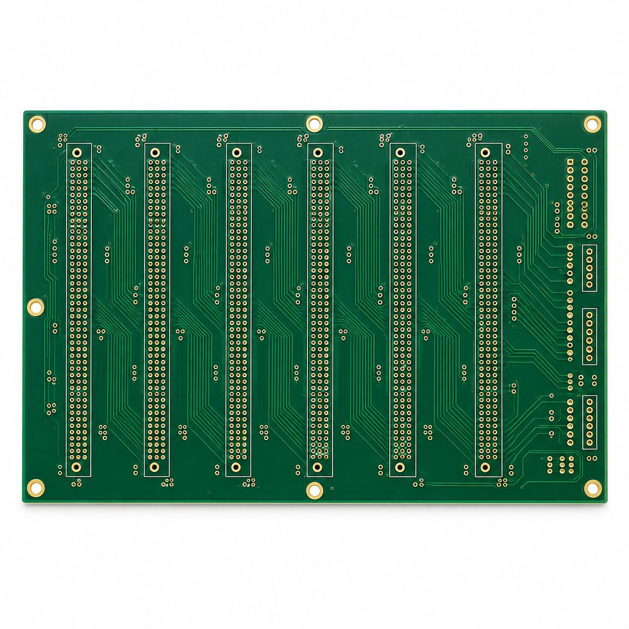
Networking & Backplanes
Loss budget, long channels, via transitions and layer count can drive selection toward lower-loss laminate families.
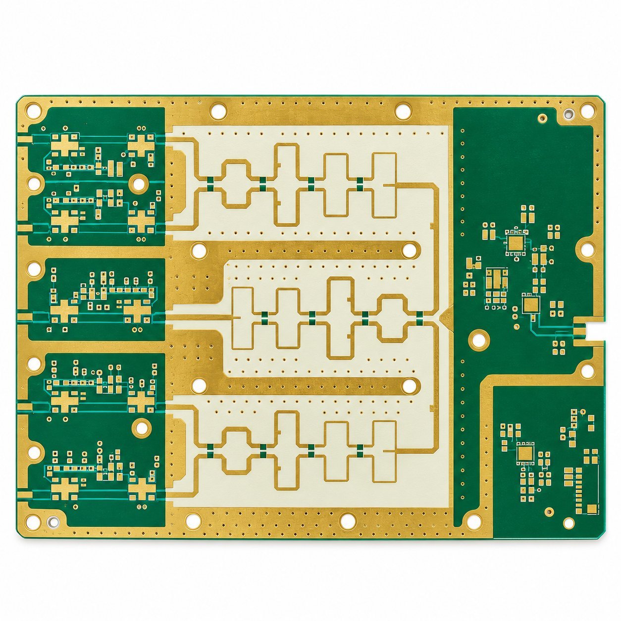
RF, 5G & Microwave
Stable dielectric properties, controlled thickness and conductor loss become central as frequency increases.
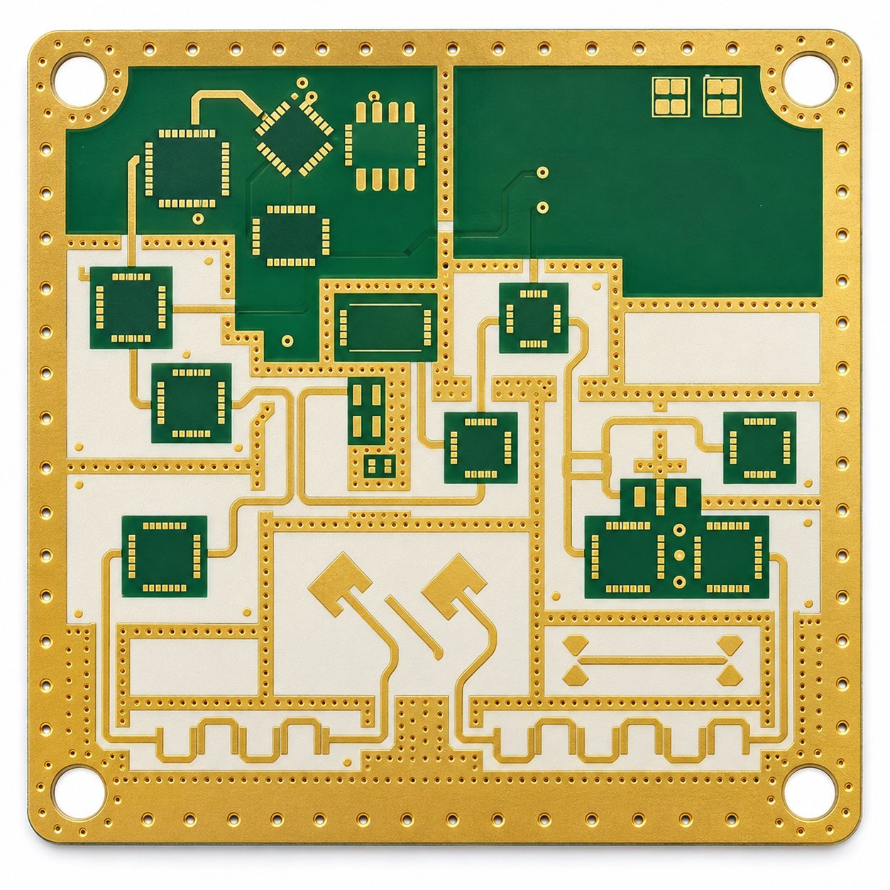
Automotive Radar
Millimeter-wave designs require careful control of dielectric, copper and geometry; Astra MT77 is positioned by Isola for RF/MW and automotive radar use.
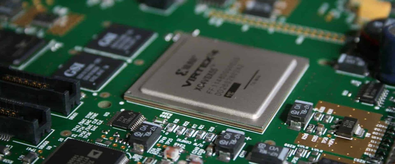
Servers & Computing
High layer count, fast serial links and repeated thermal exposure can make both signal loss and reliability part of the material decision.
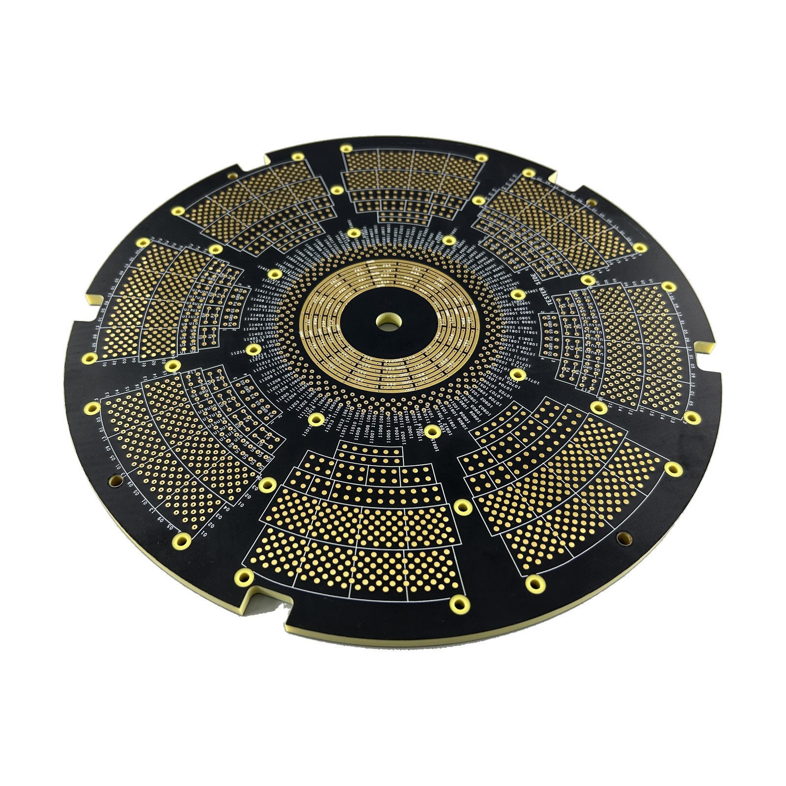
Test & Measurement
Stable, predictable electrical behavior helps support repeatable high-speed or RF signal paths in precision hardware.
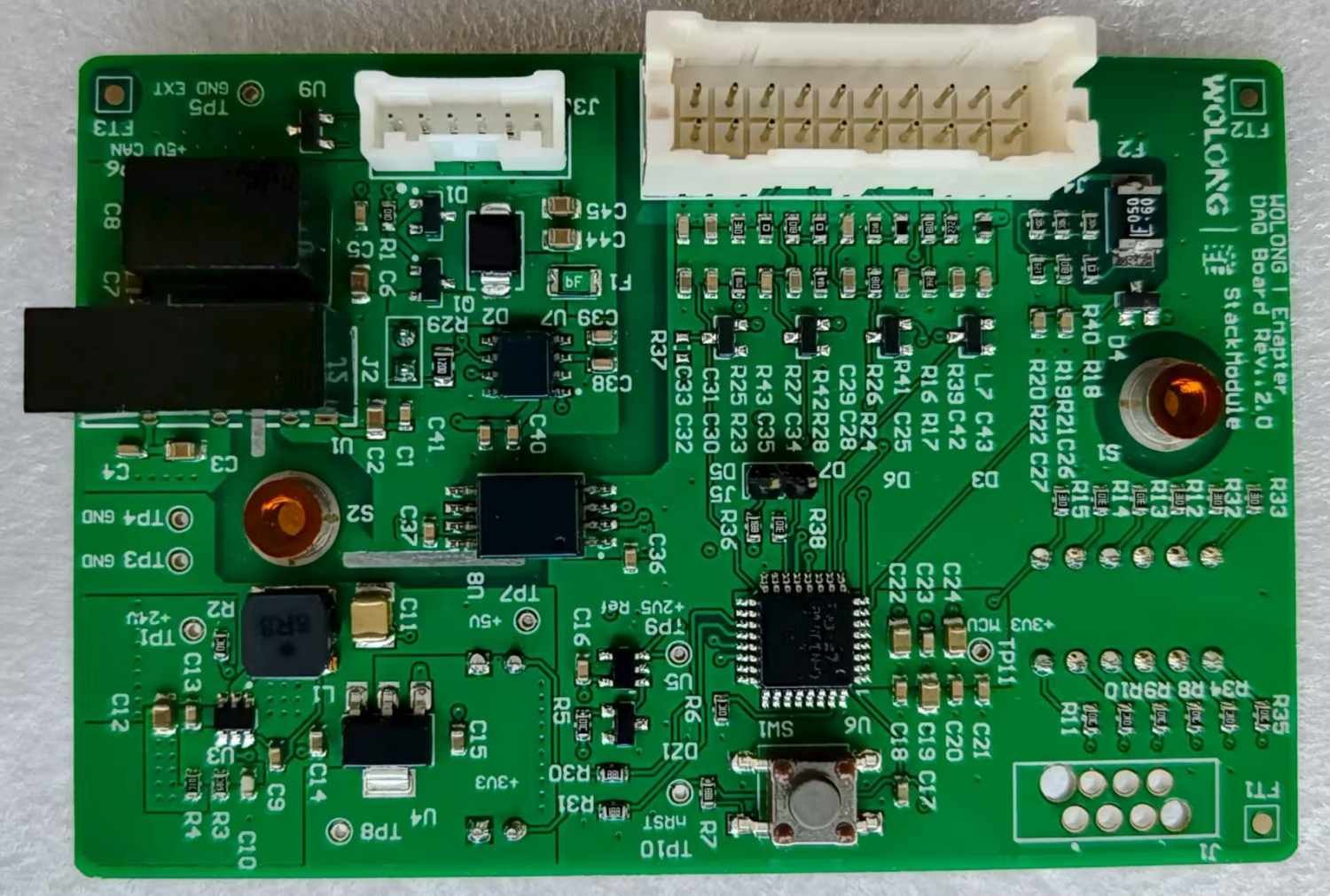
Industrial & High Reliability
CAF resistance, thermal cycling, via integrity and assembly profile may matter more than ultra-low dielectric loss.
From Material Callout to Finished PCB.
Resolve material, stackup and controlled features before release so the quotation and build are based on the same definition.
Share the Design
Provide Gerber/ODB++, drill data, drawing, quantity and the target Isola material or material-performance requirement.
Review the Stackup
Align dielectric construction, copper, finished thickness, impedance and any HDI or hybrid requirements.
Confirm Material & Quote
Confirm grade availability, substitutions if permitted, fabrication scope and project-specific inspection requirements.
Produce & Verify
Fabricate to the approved data and complete the agreed electrical, dimensional and documentation checks.
Send the Material Requirement with the Board Data.
A useful Isola PCB quotation starts with the exact design inputs. If the selected grade is not fixed yet, send the electrical and thermal targets so the material discussion is tied to the application.
Gerber or ODB++, NC drill files and fabrication drawing.
Exact Isola grade, target stackup and whether equivalent materials are allowed.
Impedance, finished thickness, copper weight/profile, surface finish and via structure.
Quantity, revision, delivery requirement and any documentation or test-report needs.
Material Questions Worth Answering Up Front
These details reduce back-and-forth and prevent a technically correct quotation from being based on the wrong material assumption.
- Is the Isola grade mandatory, or can a qualified equivalent be proposed?
- Is the headline requirement thermal reliability, insertion loss, RF performance, or all three?
- Does the impedance model already assume a specific construction or Dk method?
- Is low-profile copper required on the high-speed / RF layers?
- Are there sequential lamination, microvia, via-in-pad or hybrid-material requirements?
- Do you need material certification, impedance reports or project-specific inspection records?
Isola PCB FAQ.
What is an Isola PCB?
An Isola PCB is a printed circuit board built with an Isola laminate and prepreg system specified for the electrical, thermal, reliability or RF requirements of the design. “Isola” describes the material source/family; it does not define one universal PCB stackup.
Which Isola material should I use?
Start from the requirement: thermal reliability, high-speed digital loss, RF/microwave behavior, millimeter-wave performance, HDI processing or a combination. 370HR, FR408HR, I-Speed, I-Tera MT40, Tachyon 100G and Astra MT77 serve different performance ranges, so the right choice depends on the actual channel and manufacturing constraints.
Can I specify the exact Isola grade with no substitution?
Yes. State the manufacturer and grade clearly on the fabrication drawing or purchase specification and mark material substitution as not permitted. Exact grade, thickness and construction availability should then be confirmed during quotation.
Why can’t I use the catalog Dk directly for controlled impedance?
Dk varies with construction, resin content, test method and frequency. Controlled impedance also depends on dielectric thickness, trace geometry and copper thickness. Use values appropriate to the selected construction and align them with the fabricator’s production stackup and field-solver model.
Are all Isola materials processed the same way?
No. Material families differ in resin chemistry, copper options, glass constructions and process guidance. Lamination, drilling, desmear and dimensional compensation should follow the selected material’s current processing guidance and the factory’s characterized process.
Can Isola materials be used in hybrid stackups?
Hybrid constructions can be possible, but they require engineering review. Confirm resin compatibility, lamination conditions, dielectric geometry, copper choice, via reliability and the reason for mixing materials before the stackup is released.
What should I send for an Isola PCB quotation?
Provide Gerber or ODB++ data, drill files, fabrication drawing, target stackup, Isola grade or material-performance requirement, copper and finished-thickness targets, impedance requirements, surface finish, quantity and any inspection or report requirements.