GlobalWellPCBPCB & PCBA Manufacturing
Rogers PCB Manufacturing

Rogers PCB for RF, Microwave & High-Frequency Designs.

Build low-loss RF and microwave circuits with material selection, controlled-impedance stackup review and fabrication requirements coordinated before production.
RO4000 Series RO3000 Series RT/duroid Hybrid Stackups
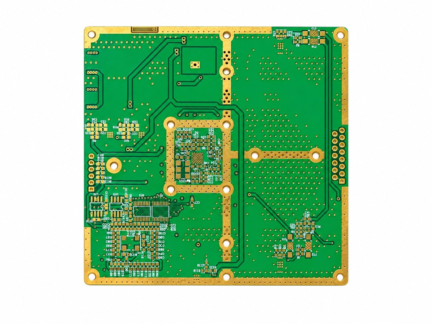
Front view of a green PCB with gold pads and mounting holes on a white background
Front-view PCB sample on a white background.
01
Low-Loss Material OptionsChoose the laminate around frequency, loss, Dk and thermal needs.
02
Controlled Impedance ReviewCoordinate geometry, dielectric thickness, copper and reference planes.
03
Hybrid Construction SupportReview Rogers and compatible non-Rogers layers as one stackup.
What Is a Rogers PCB?

The Substrate Becomes Part of the RF Design.

A Rogers PCB uses one or more circuit materials produced by Rogers Corporation. These laminate families are engineered for electrical characteristics such as controlled dielectric constant, low dielectric loss and performance stability that matter in RF, microwave, millimeter-wave and other signal-sensitive designs.

The material name alone is not enough to define a build. A manufacturable Rogers PCB also depends on the exact grade, dielectric thickness, copper type and weight, bonding system, reference-plane spacing, finished thickness, surface finish, via construction and impedance targets.
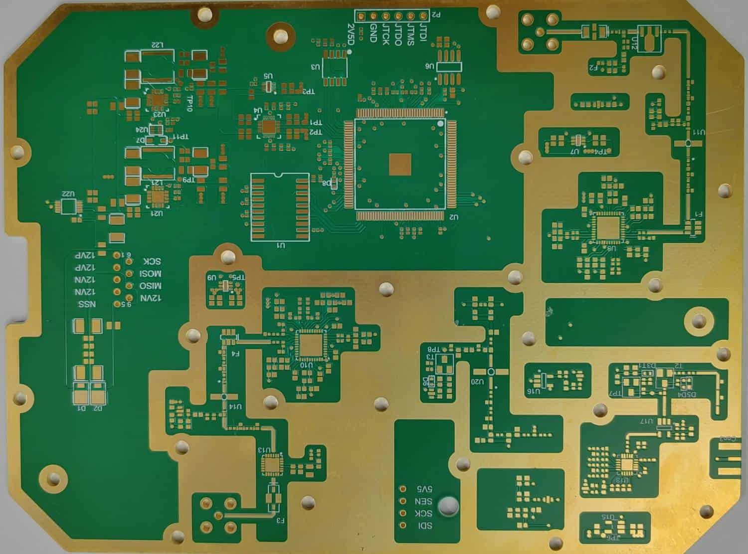
RF and microwave front ends
Antenna and feed networks
Radar and ADAS electronics
Low-loss high-speed interconnects

This page compares Rogers material families. For fabrication inputs, stackup review and agreed verification scope, see RF PCB fabrication and stackup review.

Why Rogers Materials

Choose the Material Around the Electrical Problem.

Rogers offers multiple laminate families. The best choice is the one that fits your frequency, loss budget, dielectric constant, thermal environment and fabrication strategy.

01 / Dk

Controlled Dielectric Properties

Material Dk is central to transmission-line impedance, phase length and RF structure dimensions. Use the design and process values specified for the selected laminate.

02 / LOSS

Low Dielectric Loss

Low dissipation factor can reduce dielectric contribution to insertion loss, especially as frequency and electrical path length increase.

03 / THERMAL

Thermal & Dimensional Stability

CTE and temperature behavior influence layer registration, plated-hole reliability and electrical stability under operating and assembly temperatures.

04 / STACKUP

Material-Specific Stackups

RO4000, RO3000, RT/duroid and TMM families are not interchangeable. Bonding, drill, plating and lamination details should follow the selected system.

Rogers Material Families

Compare Common High-Frequency Laminate Options.

Values below are representative published material properties. Always confirm the current Rogers datasheet and the exact construction used for your design.

Material Family Process Dk Typical Df @ 10 GHz Key Selection Point
RO4003C™ RO4000 3.38 ± 0.05 0.0027 Low-loss hydrocarbon/ceramic laminate with FR-4-like processing; not UL 94 V-0 rated.
RO4350B™ RO4000 3.48 ± 0.05 0.0037 Widely used RF laminate with UL 94 V-0 flammability rating.
RO3003™ RO3000 3.00 ± 0.04 0.0010 PTFE/ceramic system with strong Dk stability for applications including 77 GHz automotive radar.
RO3010™ RO3000 10.20 ± 0.30 0.0022* High-Dk option for compact RF structures, resonators and size-sensitive microwave designs.
RT/duroid® 5880 RT/duroid 2.20 ± 0.02 0.0009 Very low-loss reinforced PTFE laminate for broadband and high-frequency applications.
TMM® 10i TMM 9.80 ± 0.245 0.0020 High-Dk thermoset microwave material with low thermal coefficient of Dk and copper-matched CTE characteristics.

*RO3010 value shown as a typical published family value; verify the latest Rogers datasheet for the exact test method and grade. Material trademarks belong to Rogers Corporation.

01 / RO4000

RO4003C & RO4350B

A practical starting point for many RF and microwave boards that need stable dielectric performance and manufacturable multilayer or hybrid constructions.

Dk range shown3.38–3.48
Typical Df0.0027–0.0037
02 / RO3000

RO3003 & High-Dk RO3000 Options

PTFE/ceramic laminates for frequency- and temperature-sensitive RF structures, including mmWave and automotive radar designs.

RO3003 Dk3.00 ± 0.04
RO3003 Df0.0010
03 / SPECIALTY RF

RT/duroid & TMM

RT/duroid 5880 is a PTFE composite; TMM is a ceramic/hydrocarbon/thermoset composite. Select the exact family for its electrical, mechanical and processing requirements.

RT/duroid 5880 Df0.0009
TMM10i Dk9.80 ± 0.245
RO4003C vs RO4350B

Similar Processing. Different Trade-Offs.

RO4003C and RO4350B are often compared because both belong to the RO4000 family and can be processed with methods similar to standard epoxy/glass fabrication.

RO4003C has the lower published dissipation factor of the two, while RO4350B adds UL 94 V-0 flammability compliance. The decision should be based on the complete electrical, regulatory and fabrication requirement—not one number.

Do not substitute one Rogers grade for another without reviewing impedance, Dk, loss, thickness availability, flammability and the approved stackup.
PropertyRO4003CRO4350B
Process Dk3.38 ± 0.053.48 ± 0.05
Design Dk3.553.66
Typical Df @ 10 GHz0.00270.0037
Z-axis CTE46 ppm/°C32 ppm/°C
Thermal Conductivity0.71 W/m·K0.69 W/m·K
UL 94 RatingNon-FRV-0
Lead-Free CompatibleYesYes

Manufacturer source: RO4003C / RO4350B data sheet, page 3. Process Dk and Df use clamped stripline at 10 GHz / 23°C; design Dk uses differential phase length at 8–40 GHz. RO4350B at 4 mil has a different process Dk (3.33 ± 0.05), and LoPro constructions have separate qualifications. Confirm the exact construction before using these typical values.

Rogers vs FR-4

Use High-Frequency Material Where It Creates Value.

FR-4 covers a broad family of materials, so performance varies by grade. For RF designs, compare the actual laminate datasheets rather than treating all FR-4 as one material.

Design AreaRogers High-Frequency LaminatesTypical FR-4 Strategy
Dielectric ControlFamilies are engineered with tightly characterized Dk behavior for RF/microwave design.Depends strongly on the specific FR-4 grade, resin system, glass style and test method.
Dielectric LossLow-loss grades are available for insertion-loss-sensitive transmission lines.Standard grades may be acceptable at lower frequencies or short routes; low-loss FR-4 options also exist.
Cost StrategyUse where electrical performance justifies the material and process cost.Often more economical for digital, power and non-RF layers.
Hybrid StackupCan be used on RF-critical layers in an engineered hybrid construction.Can occupy non-RF layers when bonding and stackup compatibility are confirmed.
Process PlanningVaries by laminate family; PTFE systems can require different handling than RO4000 materials.Well-established conventional PCB processing, depending on grade and construction.
Design & Stackup Review

RF Performance Starts Before the Board Reaches Production.

For Rogers PCB manufacturing, laminate selection and trace geometry cannot be separated. Share the intended stackup and controlled-impedance requirements early enough to verify dielectric thickness, copper and manufacturable geometry.

  • Define the exact Rogers grade.Specify the laminate family, material code and dielectric thickness—not only “Rogers PCB.”
  • Separate process Dk and design Dk.Use the value and test basis recommended for the selected design method.
  • Plan reference planes and transitions.Keep return paths clear, minimize unnecessary RF layer changes and review via structures around high-frequency transitions.
  • Include copper and surface finish.Copper thickness, copper profile and finish can influence conductor loss and RF behavior.
Manufacturing Review

Control the Variables That Move RF Performance.

Exact capability limits depend on the selected material, thickness, copper, stackup and design. Confirm the project-specific process window before release.

01 / MATERIAL

Material Traceability

Confirm the exact laminate and bonding material called out in the approved stackup and purchasing documentation.

02 / IMPEDANCE

Controlled Impedance

Review dielectric thickness, line geometry, copper thickness and reference planes before finalizing impedance geometry.

03 / MECHANICAL

Drill & Via Process

Match drilling, desmear/plasma, plating and via construction to the selected laminate family and reliability requirements.

04 / INSPECTION

Verification Plan

Define electrical testing, dimensional checks, coupons, impedance verification and any cross-section requirements in advance.
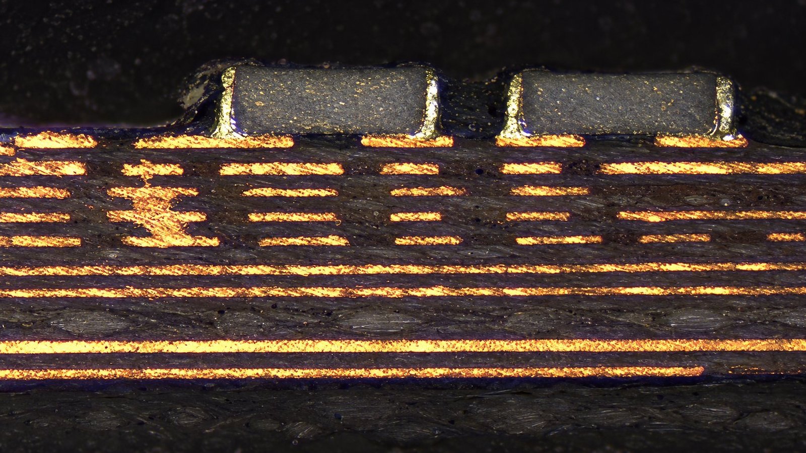
PCB cross-section showing copper layers and plated hole walls
PCB cross-section inspection.
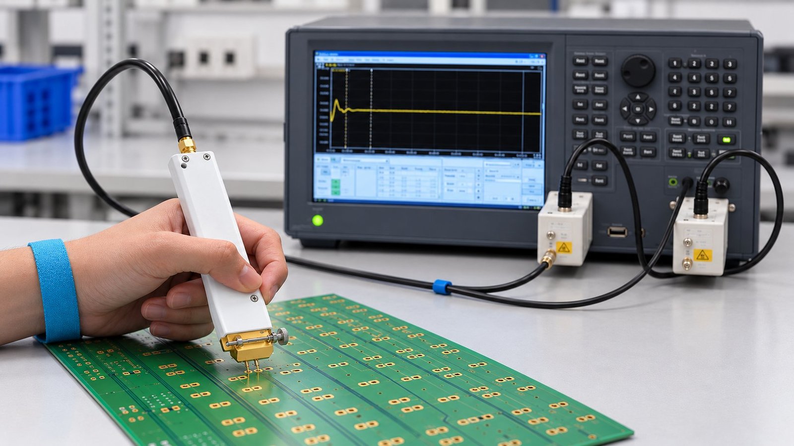
PCB impedance testing with a handheld probe and a measurement instrument
PCB impedance testing.
Applications

Where Rogers PCB Materials Are Commonly Evaluated.

Application alone does not determine the material. Frequency, loss budget, temperature, power, mechanical reliability and cost still need to be reviewed together.

01 / WIRELESS

5G & Wireless Infrastructure

RF front ends, base-station circuits, filters, antenna networks and other controlled-impedance signal paths.

02 / RADAR

Automotive Radar & ADAS

Millimeter-wave radar sensors and antenna structures where Dk stability and RF loss are design-critical.

03 / AEROSPACE

Satellite & Aerospace RF

Microwave communication, antenna, navigation and radar electronics with tight electrical requirements.

04 / RF POWER

Power Amplifiers

RF power circuitry where dielectric loss, thermal behavior and copper design need coordinated review.

05 / TEST

Test & Measurement

Broadband fixtures, RF modules and measurement hardware that require predictable transmission-line behavior.

06 / DIGITAL

High-Speed Mixed-Signal

Selective use of low-loss laminate on high-speed or RF-critical layers within an engineered multilayer stackup.

Project Workflow

From Material Callout to Finished Rogers PCB.

A clean quotation starts with complete material and stackup information—not just a Gerber package.

Share Design Data

Send Gerber or ODB++, drill files, quantity, stackup, material grade, copper and surface finish.

Review Stackup

Check material availability, thickness, bonding system, impedance geometry and critical process requirements.

Confirm & Fabricate

Lock the approved file revision, stackup and controlled requirements before production begins.

Inspect & Deliver

Complete the agreed electrical, dimensional and impedance checks, then package and ship the finished boards.

Request a Rogers PCB Quote

Give the Engineering Team the Inputs That Matter.

The more complete the stackup and RF requirements are, the fewer assumptions are needed during quotation and DFM review.

Fabrication Data

Gerber / ODB++, NC drill, fabrication drawing and panel or individual-board requirements.

Material & Stackup

Exact Rogers material grade, dielectric thickness, bonding material, copper weight and finished board thickness.

RF Requirements

Controlled impedance, critical transmission lines, target tolerances, coupons and any RF test requirements.

Commercial Inputs

Quantity, delivery target, prototype / production stage and any documentation requirements.

Common Questions

Rogers PCB FAQ.

What is a Rogers PCB?

A Rogers PCB is a printed circuit board that uses one or more high-frequency laminate materials from Rogers Corporation, such as RO4000, RO3000, RT/duroid or TMM materials. The laminate is part of the electrical design, so the exact grade and construction should be specified.

What is the difference between RO4003C and RO4350B?

Both are RO4000-series laminates. RO4003C has a process Dk of 3.38 ± 0.05 and a typical dissipation factor of 0.0027 at 10 GHz. RO4350B has a process Dk of 3.48 ± 0.05, a typical dissipation factor of 0.0037 at 10 GHz, and UL 94 V-0 flammability rating.

Can Rogers material be combined with FR-4?

Yes. Hybrid stackups can place Rogers material on RF-critical layers and use compatible non-Rogers materials elsewhere. The bonding system, CTE, dielectric thickness, copper, symmetry and lamination process should be reviewed as a complete stackup.

Which Rogers material is best for 77 GHz radar?

Rogers identifies RO3003 as a material used in automotive radar and ADAS applications, including 77 GHz. The final material choice still depends on the antenna or transmission-line design, thickness, loss target, thermal environment and manufacturing constraints.

Do I use process Dk or design Dk for impedance calculations?

Use the dielectric value appropriate to the selected material, test method and modeling approach. Rogers publishes both process and design values for some materials. Your impedance model and stackup should state which value is being used.

What files are needed for a Rogers PCB quote?

Provide Gerber or ODB++ data, drill files, stackup, exact Rogers grade, dielectric thickness, copper requirements, finished thickness, surface finish, quantity and all controlled-impedance or RF-specific requirements.

Technical note: Typical material data is linked to Rogers product information in the comparison table. Sources checked 14 October 2026. Always verify the latest official datasheet, test method and material availability before design release or production. Rogers®, RO4000®, RO3000®, RT/duroid® and TMM® names and marks are associated with Rogers Corporation. GlobalWellPCB is not presented here as Rogers Corporation or as an authorized Rogers representative.
Scroll to Top