Rigid-Flex PCB Manufacturing
Rigid-flex PCB manufacturing support for compact three-dimensional assemblies. Bring rigid sections, flexible connections, bend zones and assembly requirements together in one board design.
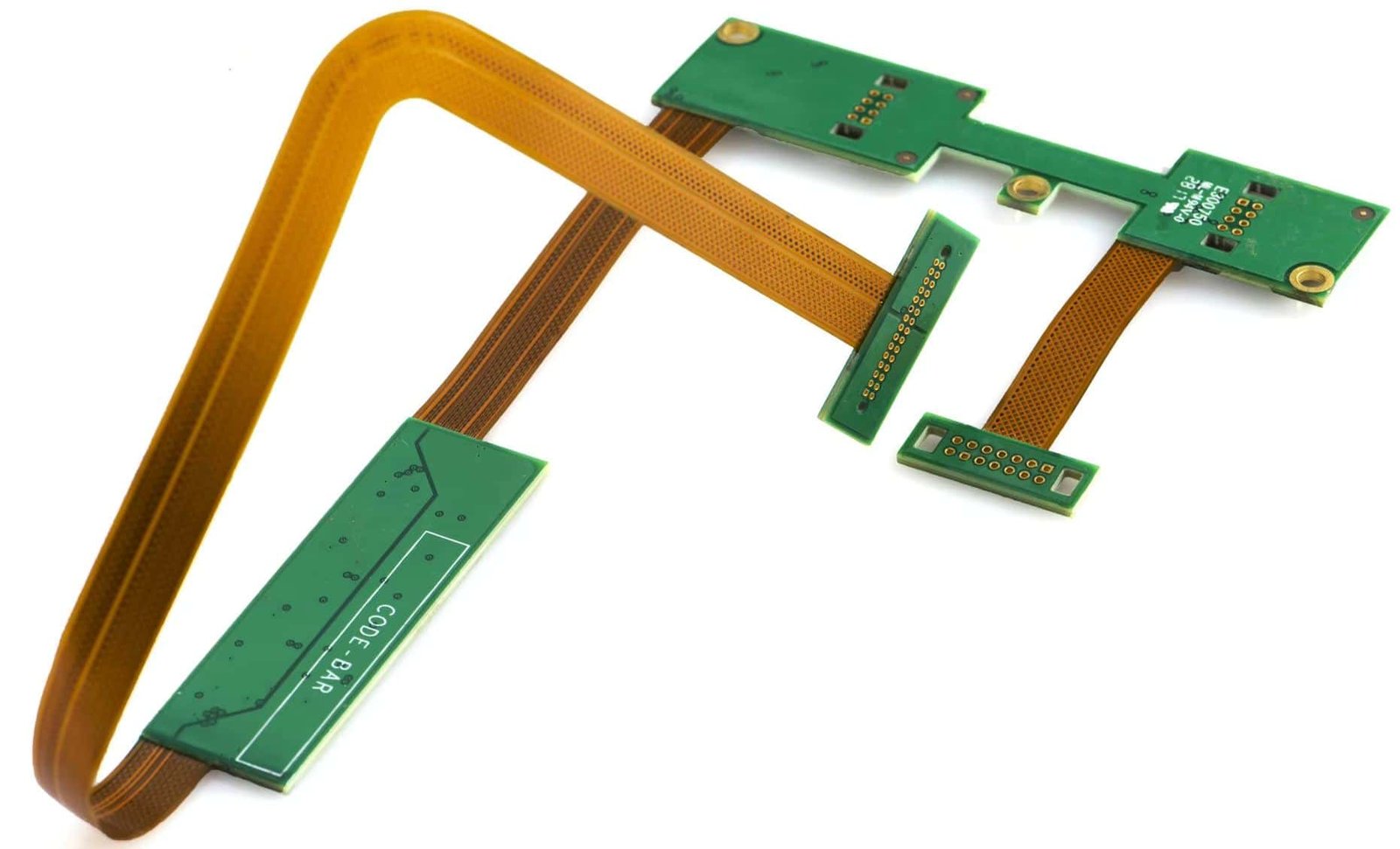
Quick answer: A rigid-flex PCB integrates rigid circuit board areas and flexible circuit areas into one connected PCB. The rigid areas typically support components and connectors, while the flexible areas route signals through folded, hinged or moving product spaces.
Start an Engineering ReviewWhat Is a Rigid-Flex PCB?
A rigid-flex PCB is a single printed circuit board that combines rigid laminate sections with flexible circuit sections. This construction allows the electrical connection to follow the mechanical shape of the product.
Rigid areas can provide a stable platform for components, connectors and mechanical mounting. Flexible areas can route signals through bends, hinges, narrow spaces or multiple planes without relying on a separate cable and connector assembly.
Rigid-flex PCB = rigid circuit board functionality + flexible interconnection in one integrated PCB structure.
- Suitable for compact and three-dimensional packaging
- Useful when a cable or connector assembly adds complexity
- Requires dedicated attention to bend zones and transition areas
One Interconnect Structure for Complex Product Geometry
Rigid-flex design is most valuable when electrical routing and mechanical packaging need to be considered together.
Use Available Internal Space
Flexible sections can route around product features and connect separated rigid areas within a compact enclosure.
Reduce Separate Cable Assemblies
An integrated board structure can reduce reliance on separate cables, connectors and manual interconnection steps.
Improve Assembly Consistency
A controlled board-to-board interconnect can simplify product assembly when the mechanical design is validated.
Support Controlled Bending
Flexible zones can be designed for static folds or specified movement, depending on the application and construction.
Maintain a Defined Electrical Path
Routing, grounding, impedance and shielding requirements can be considered across the complete rigid-flex structure.
Connect Design and Manufacturing Review
Early review of bend zones, stack-up and transitions can help identify risks before fabrication and assembly.
Where Rigid-Flex PCBs Are Used
Rigid-flex PCBs are commonly evaluated for products where space, weight, movement or interconnection reliability influences the electrical and mechanical design.
Medical Electronics
Compact monitoring equipment, handheld devices, sensors and instruments with constrained internal packaging.
Aerospace & Avionics
Electronics where packaging efficiency, weight management and controlled interconnects are key design factors.
Industrial Equipment
Control systems, instrumentation and equipment with moving covers, hinged interfaces or limited enclosure space.
Consumer Electronics
Compact products that need to route signals through folded internal structures or narrow mechanical spaces.
Rigid-Flex PCB Compared with Other Interconnect Options
The right solution depends on mechanical movement, available space, assembly method, electrical requirements and expected production volume.
| Evaluation Area | Rigid-Flex PCB | Rigid PCB + Cable | Flexible PCB |
|---|---|---|---|
| Construction | Rigid and flexible sections integrated into one board structure. | Separate rigid boards connected with a cable and connector assembly. | Primarily flexible construction with limited rigid support areas. |
| Packaging | Suitable for folded or three-dimensional product layouts. | Requires additional cable routing and connector space. | Suitable for flexible routing where component support is minimal. |
| Assembly | Can reduce separate interconnection and cable installation steps. | Includes separate cable, connector and assembly operations. | May require stiffeners or brackets to support components. |
| Mechanical Movement | Designed around specified static folds or controlled movement. | Depends on cable construction, routing and connector retention. | Flexible routing possible, but component zones need mechanical support. |
| Best Use Case | Compact or 3D layouts where rigid and flexible sections are both required in one board. | Products where rigid boards can be connected separately and cable routing is manageable. | Products where flexible routing is the primary need and component mounting is external. |
| Development Focus | Early review of bend zones, stack-up transitions and mechanical validation. | Cable routing design, connector selection and assembly documentation. | Mechanical support planning for component and connector areas. |
On smaller screens, scroll this table horizontally to compare all columns.
Rigid-Flex PCB Design Considerations
Rigid-flex design requires coordination between electrical routing, mechanical packaging and manufacturing constraints. These areas should be reviewed early in the design cycle.
Bend Zone Definition
Define the bend area, bend direction, bend radius and whether the bend is a static fold, a dynamic flexing zone or an installation bend.
Trace Routing in Flex Areas
Route traces perpendicular to the bend axis where possible. Avoid sharp corners, use curved traces and distribute copper evenly across the flexible section.
Rigid-to-Flex Transition
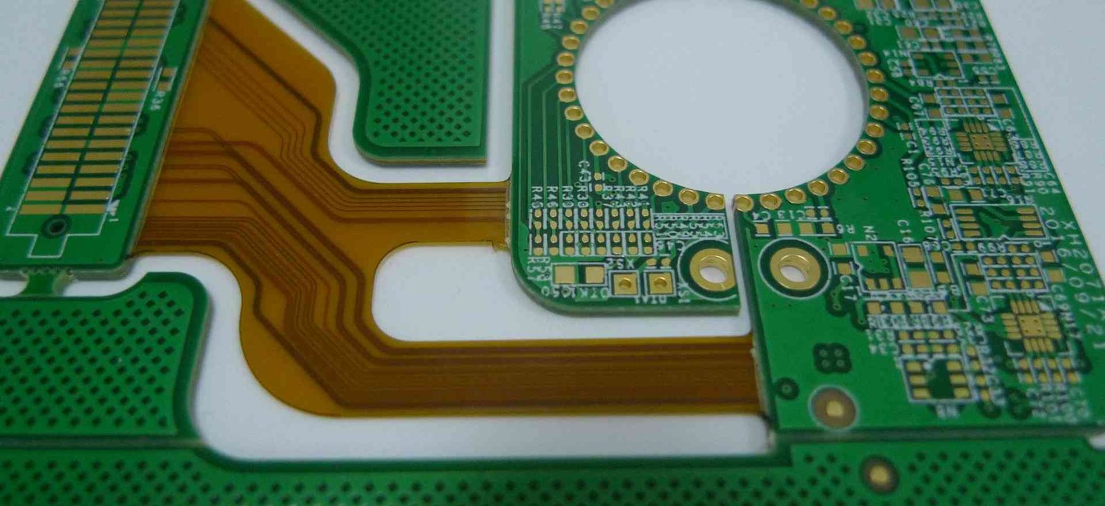
Plan the transition area where rigid and flexible sections meet. Avoid placing vias, components or mounting holes directly at the transition zone.
Stack-Up Coordination
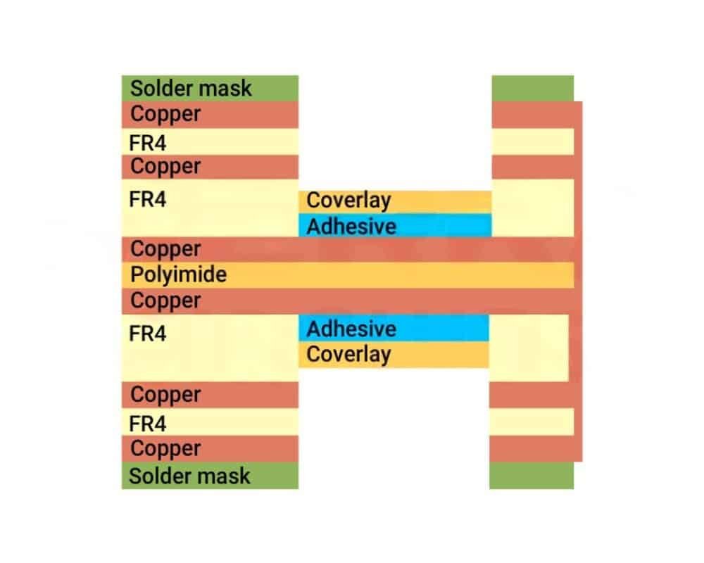
Define the layer structure for rigid and flexible areas separately. Flexible areas typically use fewer layers. Stack-up affects bend performance, impedance and yield.
Component Placement
Place components on rigid sections unless the flexible area has been specifically designed, supported and validated for that component and assembly process.
Stiffener and Support Areas
Identify stiffeners needed for connectors, components and handling. Specify the material, thickness, adhesive, location and supported side, and keep stiffener edges clear of active bending where practical.
Rigid-Flex PCB Materials and Stackup
Polyimide and Copper
Specify the flex dielectric, copper foil grade and finished thickness against the bend duty and electrical requirements.
Rigid Laminate
Coordinate the rigid material with the assembly profile, dielectric targets and overall construction.
Coverlay
Define openings, overlap and terminations at the transition; distinguish coverlay from rigid-area solder mask.
Controlled-Flow Prepreg
Review low-flow or no-flow bonding materials where the construction requires control of resin migration.
Specify rigid and flexible regions separately in your stackup. Isola's controlled-flow prepreg guidance describes bonding options. Confirm the exact material grade and availability with us for your order.
What Affects Rigid-Flex PCB Cost?
Rigid and flex layer counts, bonding sequence and via architecture.
Installed radius, motion profile, cycle target and qualification.
Rigid islands, flex length, outline and manufacturing panel use.
Specified laminate, foil, coverlay, stiffeners and assembly finish.
Prototype quantity, production volume, coupons and reporting scope.
Compare the complete installed interconnect, including cables, connectors, assembly and serviceability. There is no universal price or lead-time multiplier for rigid-flex PCB fabrication.
What to Confirm With a Rigid-Flex PCB Manufacturer
| Requirement | What to provide and agree |
|---|---|
| Layer structure | Rigid and flex copper layers, material interfaces and bonding sequence. |
| Finished thickness | Separate thickness and tolerance for each rigid and flexible region. |
| Bend drawing | Radius, axis, angle, installed shape and installation or dynamic use. |
| Copper and impedance | Foil grade, finished copper, return paths and controlled nets. |
| Vias and transitions | Layer connections, pads, filled vias and transition keepouts. |
| Coverlay and stiffeners | Material, openings, adhesive, alignment and component support. |
| Surface finish | Assembly-compatible finish; wire bonding needs separate verification. |
| Quantity and acceptance | Revision, prototype or production quantity, tests and reports. |
On smaller screens, scroll this table horizontally to compare all columns.
Rigid-Flex PCB Inspection and Qualification
Define the Acceptance Evidence
- Material and revision identification for the approved construction.
- Visual and dimensional checks of rigid, flex and transition areas.
- Continuity and isolation tests; impedance verification when specified.
- Construction coupons or microsections where required by the quality plan.
- Representative bend or thermal-cycle tests when the end-use requires qualification.
Fabrication electrical testing does not prove a particular dynamic flex life. Agree class, revision, sampling, environmental conditions and acceptance criteria separately.
Files for a Rigid-Flex PCB Quote
Fabrication Package
Gerber, ODB++ or another agreed format, drill data, outline and controlled revision.
Mechanical and Bend Data
Flat and installed drawings, bend zones, radius, movement, stiffeners and keepouts.
Purchasing Specification
Materials, copper, finish, quantity, target schedule, test scope and assembly data if required.
For a rigid-flex prototype, identify what must be demonstrated before production release. A rigid flexible PCB quotation needs a coordinated mechanical and electrical package, not only artwork.
Rigid-Flex PCB Frequently Asked Questions
What is a rigid-flex PCB?
A rigid-flex PCB combines rigid circuit board sections with flexible circuit sections in one interconnected PCB structure. The rigid areas support components while the flexible areas provide controlled bending and electrical connection.
When should I use a rigid-flex PCB instead of a rigid PCB and cable?
A rigid-flex PCB is worth considering when the product has limited internal space, repeated movement, complex 3D packaging, connector-reduction goals, or a need for a more integrated interconnect structure. Separate cables and connectors may be more practical when rigid boards can be routed independently and cable replaceability matters.
What files are needed for a rigid-flex PCB quotation?
Useful quotation data includes Gerber, ODB++ or IPC-2581 files, NC drill data, stack-up information, fabrication drawings, bend-zone drawings, quantity, target date, surface finish, impedance requirements and testing requirements.
How should the bend area be specified?
The bend area should identify the bend direction, bend type (static fold or dynamic flexing), expected movement, bend radius or mechanical constraint, keep-out areas, and any required stiffener or coverlay details. A mechanical drawing or 3D model showing the folded or installed state helps manufacturing review.
Can components be placed on a rigid-flex PCB?
Components are normally placed on rigid sections unless the flexible section has been specifically designed and validated for that component, assembly method and mechanical condition. Placing components on flexible areas requires additional stiffener support and careful evaluation of the assembly process and expected movement.
What is the difference between adhesive and adhesiveless construction?
Adhesive-based flex laminates include an adhesive between the copper and film. Adhesiveless copper-clad constructions omit that separate adhesive layer. Compare the exact material grades, thicknesses, electrical properties and process requirements; neither label alone proves reliability.
What surface finish is recommended for rigid-flex PCBs?
Choose the finish from the assembly, storage and contact requirements. ENIG can be considered for solderable pads, while any wire-bonding requirement needs verification of the bond process and finish; ENEPIG may be evaluated where appropriate. Do not assume every ENIG finish is suitable for every wire-bonding process.
What affects rigid-flex PCB cost and lead time?
Cost and lead time are affected by layer count, material system, rigid-flex construction, bend requirements, via structure, board size, surface finish, testing, order quantity and assembly requirements. Rigid-flex PCBs generally have higher unit cost and longer lead time than standard rigid PCBs due to additional fabrication complexity.
Can rigid-flex PCBs be tested before assembly?
Bare-board continuity and isolation can be checked before assembly. Impedance, microsections or other evidence must be specified when required. These checks do not replace installed bend-life, thermal or end-product qualification.
What is the typical lead time for rigid-flex PCB fabrication?
Lead time depends on layer count, construction complexity, material availability, order quantity and current production schedule. Prototype rigid-flex boards typically require more time than standard rigid PCBs. Production lead time should be confirmed during the quotation stage for the specific project.
Technical References and Scope
Explore the material and design references below to compare construction options. Ask us to confirm the selected material, processes and delivery requirements for your design.
- All Flex: rigid-flex construction and bend-design guidance
- All Flex: conductor geometry and fillet guidance
- Isola no-flow and low-flow prepregs
Send your material grade, construction, applicable standards and acceptance requirements with your enquiry so we can prepare a quotation for your board.