
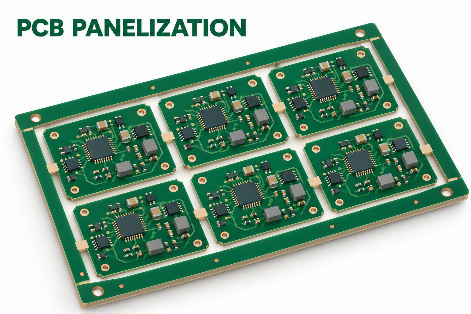
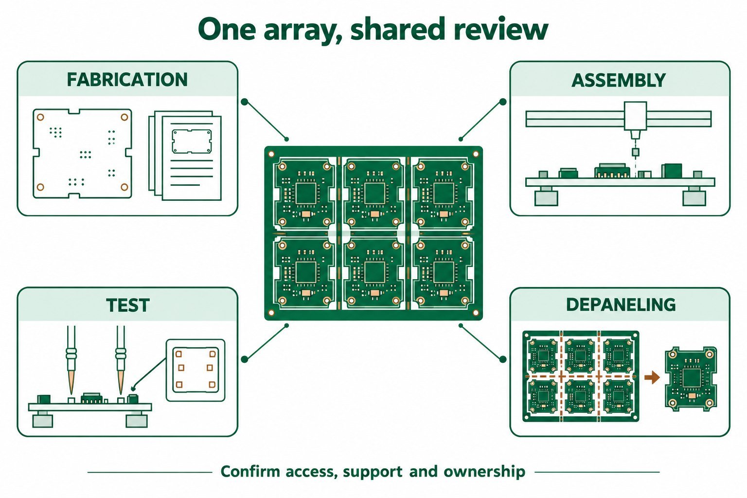
PCB panelization should produce an array that the fabrication, assembly, test, and separation processes can all use. Maximizing the number of circuits in a rectangle is only one objective. The accepted panel also needs suitable handling features, component access, identification, and a separation plan that respects the finished product.
Treat the panel as a manufacturing interface with its own revision. Begin with the individual board definition, then agree how that board will be repeated, transported, supported, processed, and separated.
Distinguish the fabrication panel from the assembly array
A fabricator’s production panel and the array delivered to an assembler need not be the same object. Identify which object is under discussion before comparing dimensions, board counts, or material utilization. Otherwise, two valid answers can appear to contradict each other because they describe different stages.
Ucamco’s Gerber Job specification deliberately separates an individual PCB definition from an assembly-panel definition, which may change between production runs. That distinction is useful when controlling the design and the manufacturing array independently. Ucamco: Gerber Job Format Specification, revision 2020.01, section 2.1
Specify whether the supplier will deliver loose boards or an agreed array. Define whether order quantity counts circuits or arrays. If the assembler owns the panel layout, ask the fabricator to use that approved drawing rather than optimize it independently after quotation.
Start with the product edges and the separation path
Mark connector interfaces, overhanging bodies, sensitive components, exposed copper, mounting features, and required finished-edge conditions. These features determine where the board can be held and where separation tooling can move.
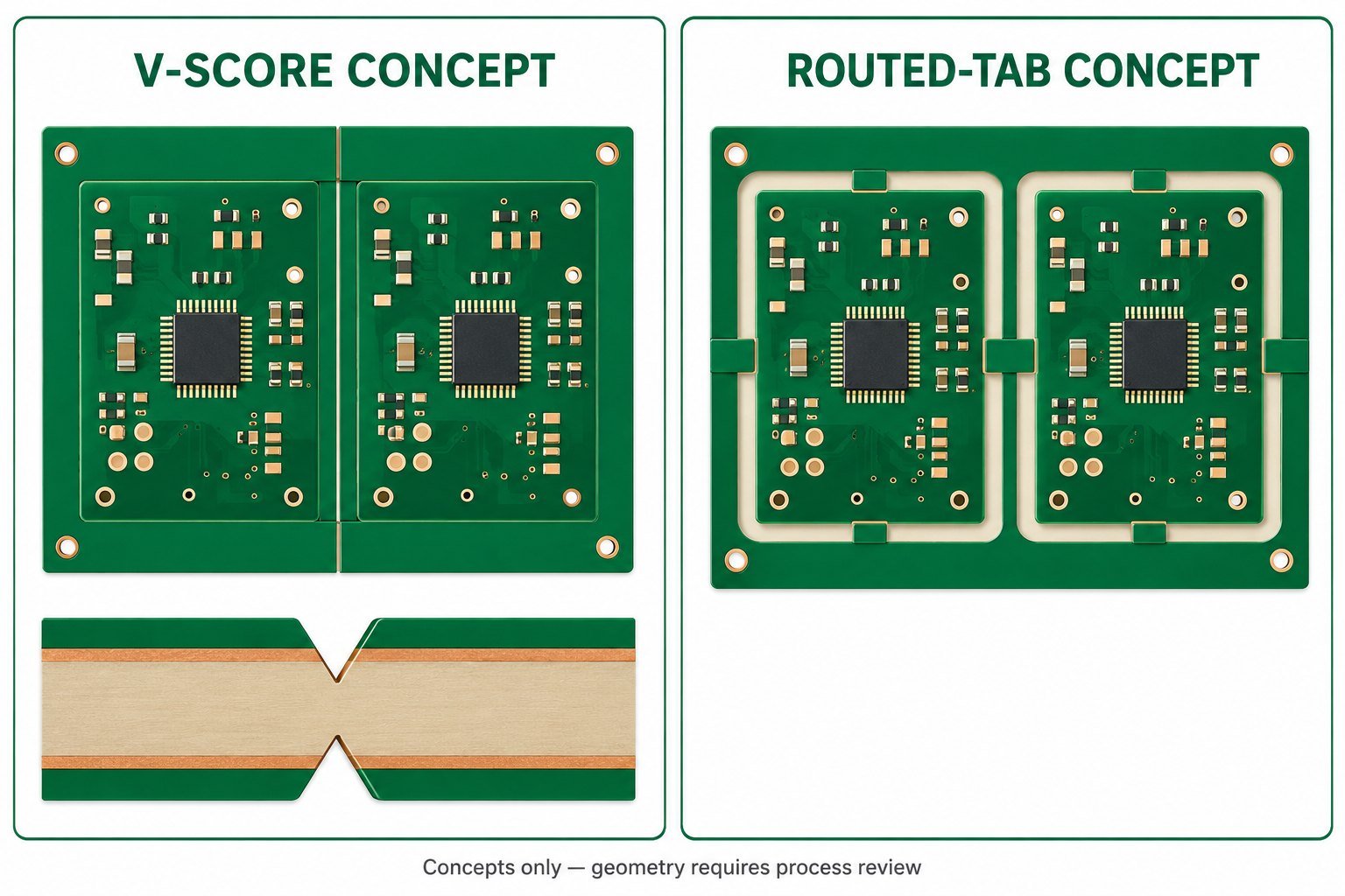
Discuss scored and routed concepts with the actual process owner. For a scoring proposal, examine the complete score path and what remains attached during processing. For a routed proposal, examine the tool envelope and the location of every supporting tab. Do not assume that a feature is acceptable because it fits in an overhead outline drawing.
Identify whether separation happens before or after functional test, coating, enclosure attachment, or another operation. A support tab that helps the SMT line may obstruct a later fixture. A connector that is accessible while boards are separate may collide with a neighbor while the array remains intact.
Review component strain where the panel will be separated
Murata documents that board bending after soldering can crack ceramic capacitors and illustrates how component orientation and local slits affect stress near board breaks. Its examples explain the mechanism, rather than supply a universal clearance for every array. Murata: Layout considerations for preventing MLCC cracking
Use that mechanism to focus the review: identify components near separation features and ask how the chosen tool, board support, and cutting sequence load those locations. Distance from a tab is one input; the part orientation and the direction in which the board bends also matter.
When the risk is unclear, request a representative separation trial with an agreed inspection or strain-assessment plan. Define the component locations and process conditions to be evaluated. A clean-looking separated edge does not, by itself, establish that nearby components avoided internal damage.
Do not change a component footprint solely to solve a panel problem without the relevant component guidance and assembly review. A panel-level change, a support change, or a different separation path may be the more appropriate candidate, depending on the product.
Assign panel features to their process owners
The following responsibility table is a proposed coordination tool. It prevents an apparently complete panel drawing from relying on unreviewed assumptions from another process.
| Panel decision | Lead reviewer | Evidence to request before release |
|---|---|---|
| Circuit orientation and repetition | Design owner with assembler | Approved individual-board revision and array drawing |
| Rails, transport edges, and support | Assembly process owner | Equipment and fixture compatibility review |
| Fiducials and tooling | Printing, placement, and inspection owners | Visibility and access on the actual panel surfaces |
| Tabs, scores, and routed paths | Fabricator and depaneling owner | Proposed geometry, tool access, support and sequence |
| Sensitive edge components | Product and assembly engineers | Part-specific constraints and any required validation |
| Test and traceability | Test and quality owners | Fixture access, circuit identity and rejected-circuit disposition |
| Delivered form and quantity | Buyer and manufacturing owner | Order definition matching the accepted panel revision |
Assign one person to integrate the answers. A collection of individually reasonable process comments still needs to become one coherent panel drawing.
Check the panel through the full process route
Walk the array through printing, placement, soldering, inspection, test, and separation in the order actually intended. Include any operation on the second side. Ask where the board is supported and whether component bodies, paste, labels, or tooling features obstruct access.
Confirm that fiducials remain usable at the operation that needs them. Their presence on a drawing does not prove that a clamp, component, or later process will leave them visible. Ask each equipment owner what geometry and surface condition its process expects, rather than prescribing an arbitrary common rail width or fiducial count.
Review the panel’s thermal and mechanical behavior with the assembly process owner. If a new array changes orientation, support, or material distribution compared with an established build, decide what process confirmation is necessary. The panel does not automatically inherit a validated soldering process merely because the individual circuit is unchanged.
For test, inspect probe or connector access and identify the stage at which every circuit receives its test identity. Decide how a failed circuit will be marked and handled while other circuits remain in the same array. This is especially important when a panel-level test report later becomes an individual-board acceptance record.
Compare alternatives using accepted output
Compare panel options on the same manufacturing route and delivered quantity. Include processing, fixtures, separation, inspection, and unusable edge space where those affect the actual quotation. Do not turn the visible area ratio into an unsupported cost or yield prediction.
An original review worksheet can list, for each candidate, the number of usable circuits, process compatibility questions, additional tooling, separation risks, and evidence still required. Keep unknown costs as unknown until quoted. A candidate with more circuits should not win automatically if it introduces an unresolved support or separation problem.
If mixed designs share an array, resolve quantity ratios, version control, and rejected-circuit handling. A change to one circuit can affect the array’s usability for the others. Make that dependency visible before relying on the arrangement for repeat supply.
Release the array and the separation instructions together
Approve a panel drawing that names the single-board revision, array revision, delivered orientation, rail and tooling features, and separation geometry. Link the relevant fixture or process instructions when they determine how the array is used.
Revisit the panel agreement when edge components, board thickness, connector placement, delivered form, or separation equipment changes. The correct result is a documented array that each process owner can use and a clear plan for verifying any unresolved risk.
References and method
AI-assisted drafting and document review informed this proposed coordination workflow. The sources cover individual-board versus array definitions and Murata’s board-bending mechanism. No actual panel, equipment envelope, component clearance, process yield, or separation trial was validated here.