10L with two flex layers
The reference describes 10L total, two flex layers, 3/3mil and impedance in the flex area.
Individual engineering example; the combination is reviewed for each project.
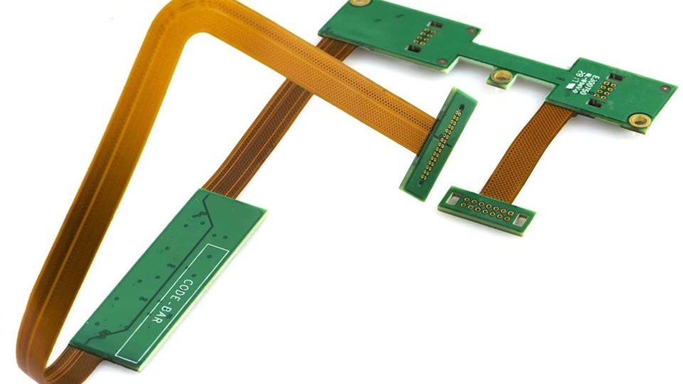
Rigid-flex capability depends on the construction in each region. Define the rigid stack, the flexible interconnect and their transition as one design, then check layer connectivity, bend shape, assembly access and acceptance requirements.
Read each value together with its board type and review conditions.
Published limits apply to their stated board type. Layer count, copper weight and minimum geometry require a combined engineering review.
Total board layer count is not the number of copper layers in a flexible zone.
On smaller screens, scroll within the table to see every column.
| Parameter | Published capability | Applies to | Review conditions |
|---|---|---|---|
| Maximum layers | 36L | Total rigid-flex construction | Provide the layer count and connectivity in each region |
| Board thickness | 0.4–8mm | Published rigid-flex board range | State rigid thickness, flex thickness and local stiffeners separately |
| Inner / outer finished copper | 6oz / 3oz | Rigid-flex published limits | Identify the copper requirement for each rigid and flexible layer |
| Inner trace / space | 3/3mil | Rigid-flex inner pattern | Copper and local layer construction |
| Outer trace / space | 3.5/4mil | Rigid-flex outer pattern | Copper, plating and protective openings |
| Mechanical / laser drilling | 0.1mm / 0.075mm | Respective hole processes | Layer span, processed depth, pad and transition position |
| Mechanical / laser aspect ratio | 12:1 / 1:1 | Respective drilling processes | Review each structure without transferring the rigid 20:1 figure |
Show exactly where every layer and protective material starts and stops.
Treat thickness-based bend figures as starting references; confirm the installed geometry and required duty.
On smaller screens, scroll within the table to see every column.
| Parameter | Published capability | Applies to | Review conditions |
|---|---|---|---|
| Process panel | 500 × 1200mm | Rigid-flex process panel | Material format, lamination tooling and margins |
| Finished board range | 10 × 10mm minimum; 22.5 × 30inch maximum | Finished outline | Region layout, tooling and handling |
| Contour tolerance | ±0.1mm | Rigid-flex contour | Specify critical transition and connector datums |
| Single-sided / double-sided radius | 3–7 × / 6–11 × flexible thickness | Respective flex-region construction | Copper, protection and bend location |
| Multilayer radius | 10–16 × flexible thickness | Multilayer flex region | Bonding arrangement and layer count |
| Dynamic radius reference | Project-specific review | Motion application reference | Define flexible-region thickness, motion and required cycle duty; no universal fatigue-life claim |
| Strain fillet width | 1.5 ±0.5mm | Rigid-flex transition reference | Confirm local drawing detail |
These examples describe individual structures in our project reference material. They do not establish a general maximum or guarantee the same combination for a new design.
The reference describes 10L total, two flex layers, 3/3mil and impedance in the flex area.
Individual engineering example; the combination is reviewed for each project.
A separate reference describes 14L total, eight flex layers, 3/3mil and impedance. It does not imply that every region uses all 14 layers.
Individual engineering example; the combination is reviewed for each project.
The reference records 16L rigid-flex with six flex layers and impedance requirements.
Individual engineering example; the combination is reviewed for each project.
A 4L example records two flex layers on the outer layer and an FR4 carrier under the flex. New carrier and removal details require their own drawing.
Individual engineering example; the combination is reviewed for each project.
Specify impedance by region and reference structure rather than by a board-wide label.
On smaller screens, scroll within the table to see every column.
| Parameter | Published capability | Applies to | Review conditions |
|---|---|---|---|
| Single-ended tolerance | ±5Ω for targets ≤50Ω; ±10% for targets >50Ω | Rigid-flex table entry | Target, net, layer, reference and region stackup |
| Differential tolerance | ±5Ω for targets ≤50Ω; ±10% for targets >50Ω | Rigid-flex table entry | Pair geometry, transitions and agreed coupon/test method |
The manufacturing package should explain both the flat product and the installed assembly.
Send a region-by-region stackup, fabrication and drill data, via spans, outline dimensions, bend drawing, stiffeners and the component placement requirements. Identify controlled-impedance routes through each region.
List the required inspection records and any assembly constraints. Resolve region thickness, transition geometry, finish and protection before releasing a construction for fabrication.
Include the drawing revision and acceptance requirements. The engineering review confirms the manufacturable combination before quotation.
The published value describes the total rigid-flex construction. The flexible-layer count and layer connectivity must be stated separately for each region.
Use the rigid-flex entries: inner 6oz and outer 3oz in the capability table, with region and construction review. The rigid-board 85oz entries do not transfer.
Identify the target, nets, layer, reference structure and flex-region stackup. Agree how transitions and coupon evidence will be evaluated.
Include a region map, full stackup, via spans, bend/installation drawing, stiffener and protection details, PCB files and assembly constraints.