PCBA DFA Check
Align the BOM, footprints, placement data and assembly process before the build starts. Resolve the details that can make an otherwise correct layout difficult to assemble.
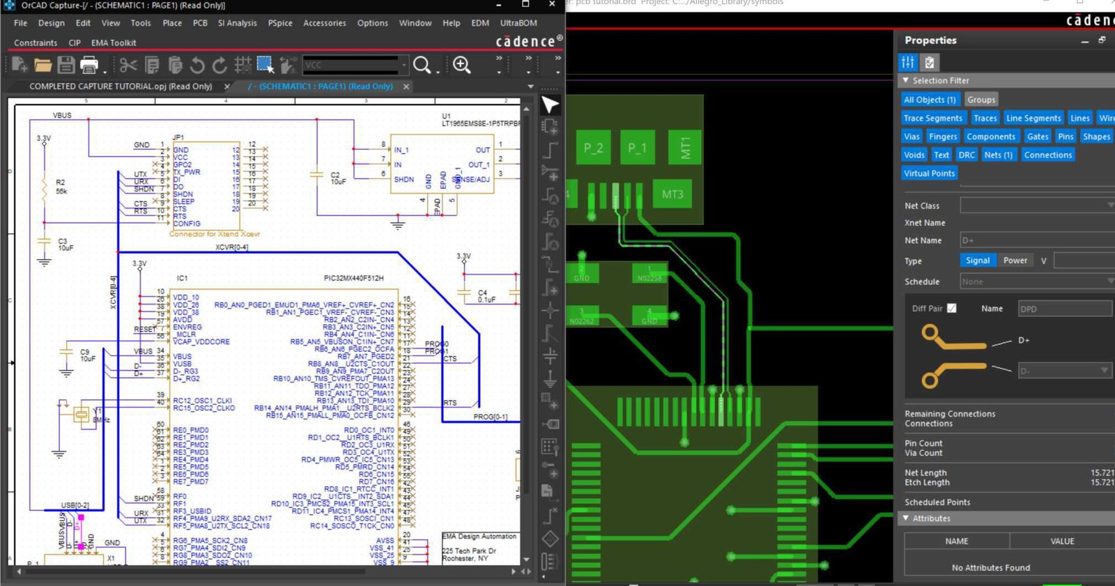
Check how the parts come together.
Design for assembly focuses on how components can be assembled into the product, rather than only how the bare board is fabricated. For a PCBA, that means reviewing the relationship between the selected parts, their land patterns, placement and the intended assembly route. [S05]
Use the GlobalWellPCB DFA discussion to identify unclear polarities, package mismatches, restricted access and instructions that are absent from the manufacturing package. Keep purchasing changes, layout changes and assembly-process decisions separate so each has the right approval.
Six practical areas for an assembly review.
Treat these as review questions. Component spacing and process limits must be checked for the actual package, tooling and assembly route—not copied from a generic design checklist.
Scroll the table horizontally to see all columns.
| Review area | What to evaluate | What to agree |
|---|---|---|
| BOM and package match | Manufacturer part number, package variant, footprint and reference designator. | Resolve mismatches, duplicate references, approved alternates and do-not-populate positions. |
| Orientation and polarity | Pin 1, connector mating direction, polarized parts and placement rotation conventions. | Provide an unambiguous assembly drawing; do not rely on a single silkscreen mark. |
| Access and clearances | Component spacing, body heights, nozzle access, inspection and rework access. | Review congested areas and tall parts with the proposed tooling. |
| Soldering strategy | Pad and paste intent, thermal-pad layouts, through-hole features and mixed-technology sequence. | Separate approved land-pattern requirements from process adjustments. |
| Panel handling | Rails, fiducials, support, edge-mounted parts and depanelization restrictions. | Show both the finished-board needs and the assembly-panel requirements. |
| Test and programming access | Accessible test points, connectors, programming headers and fixture keepouts. | Route detailed electrical coverage into a separate DFT and test-plan review. |
Tell us which features need inspection, your sampling requirements and the reports you need. We will confirm these details in your quotation.
From a clear requirement to a documented decision.
- 01
Normalize the build data
Reconcile BOM references, placement coordinates and assembly notes. Check that each populated location has an identified, approved part.
- 02
Review the assembly route
Walk through handling, printing, placement, soldering, inspection and any manual operations. Record where the proposed route needs design input.
- 03
Resolve the issue list
Give each finding a location, practical consequence and proposed action. Obtain approval for part substitutions and layout or footprint changes.
- 04
Release one matched package
Update the BOM, placement data and drawings together. Record any remaining accepted exceptions before first-article assembly.
The output is an assembly-ready decision record.
Request a review record that a buyer, designer and assembly engineer can all follow. Avoid vague findings such as “spacing problem” with no affected reference or proposed next step.
- Affected locations
- Reference designators, board side, coordinates and a marked-up view where needed.
- Verified identity
- BOM revision, actual manufacturer part number and the footprint or drawing used for comparison.
- Risk and action
- Mismatch, access concern or missing instruction, followed by the requested correction or clarification.
- Release decision
- Approved change, revised file identifiers, accepted exceptions and remaining hold points.
DFA is not a circuit redesign or test-coverage guarantee.
An assembly review does not prove that the circuit design is correct. Test access can be flagged during DFA, but an ICT or functional-test program needs its own defined coverage, fixtures and limits. Do not treat an assembly-ready drawing as a completed test plan. [S27] [S30]
PCBA DFA Check FAQs
Find answers about inspection methods, reports and approvals before placing your order.
What is the difference between PCB DFM and PCBA DFA?
PCB DFM concerns fabrication of the board. PCBA DFA concerns assembling the selected parts onto it. They share design data but address different risks, so a combined order should define both review scopes. [S05]
Can a BOM alone support a complete DFA review?
No. Pair it with placement data, board geometry and assembly instructions. Package identity without footprint and orientation information leaves important questions unanswered.
Are there universal component-spacing rules?
Use constraints for the actual components, assembly tools and inspection requirements. A spacing value suitable for one build may not provide access or rework clearance for another.
How should DNP components be specified?
Keep do-not-populate locations consistent across the BOM, placement data and assembly drawing. Identify variants explicitly instead of relying on informal email notes.
Does the review authorize a component replacement?
Not by itself. A proposed alternative needs the agreed purchasing and engineering approval, including any footprint, process, performance or test changes.
Should a revised BOM trigger another review?
Review the affected areas whenever a change alters package, orientation, population, handling or assembly instructions. Keep the approved review linked to the new configuration.
Connect the next part of your quality plan.
Technical references
- [S05]Siemens — What is DFM and DFA?
- [S27]Teradyne — TestStation Systems: In-Circuit & Functional Production Test Platform (PDF)
- [S30]NI — PCB Assembly Test Toolkit
Explore the inspection and testing references below. Include the applicable standards, acceptance criteria and required records with your enquiry so we can confirm the inspection plan for your board.