X-Ray Inspection
Review selected hidden solder-joint structures with an appropriate imaging method. Define the packages, views, acceptance criteria and reporting needed for your assembly.
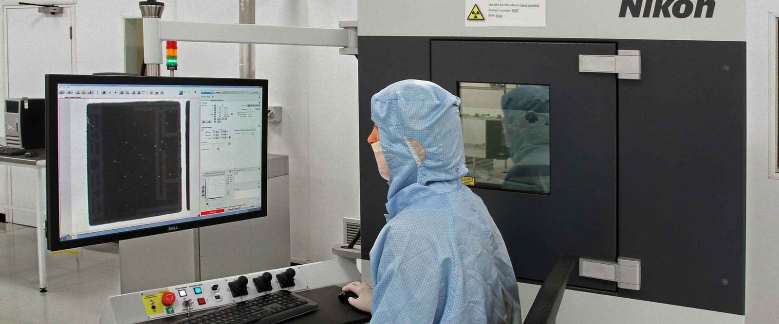
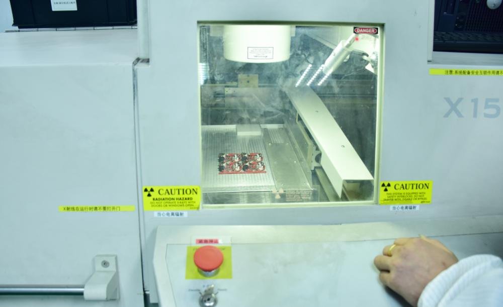
Inspect the joint beneath the package.
X-ray inspection can reveal internal assembly features that ordinary optical inspection cannot directly view. BGA, QFN and other bottom-terminated packages are common inspection targets, but detectable conditions depend on image geometry and the selected method. [S25]
For your GlobalWellPCB project, name the reference designators and the question to resolve. A request to “X-ray the board” does not establish which joints are covered, how an apparent void is measured or whether a complex feature needs additional views.
Match the view to the inspection question.
The examples below guide scope definition. They do not imply that one exposure or one equipment configuration can detect every hidden defect.
Scroll the table horizontally to see all columns.
| Review area | What to evaluate | What to agree |
|---|---|---|
| BGA and similar arrays | Review selected joint patterns, apparent bridges, missing solder or unusual joint structure. [S25] | Define the package map, joint coverage and required viewing arrangement. |
| QFN thermal and terminal regions | Review the selected thermal-pad or terminal solder distribution. | Set package-specific evaluation regions and the governing criteria. |
| Through-hole features | Selected internal solder or interconnection features may be investigated. [S26] | Agree whether the chosen image can answer the stated question. |
| 2D projection | An image combines attenuation information along the viewing path. | Consider overlap from parts and copper on other layers or the opposite side. |
| Additional views or 3D methods | Angled views or reconstruction can help separate otherwise overlapping structures. [S26] | Confirm method availability, sample suitability and the required resolution. |
| Suspected unusual joints | A suspicious image may require further examination or another method. | Do not promise universal head-in-pillow or crack detection from a single image. |
Tell us which features need inspection, your sampling requirements and the reports you need. We will confirm these details in your quotation.
From a clear requirement to a documented decision.
- 01
Locate the inspection targets
Provide component references, package information and any known defect history. Identify whether the task is screening, acceptance or targeted investigation.
- 02
Approve the imaging plan
Agree views, coverage, method, sample selection and acceptance criteria. Resolve any ambiguity about how voiding or other features will be evaluated.
- 03
Capture and review evidence
Record images with sufficient identity and context. Review uncertain indications instead of converting every image contrast change into a confirmed defect.
- 04
Disposition and follow up
Document findings, approved rework and repeat inspection where required. Recommend additional analysis when the image cannot support a reliable conclusion.
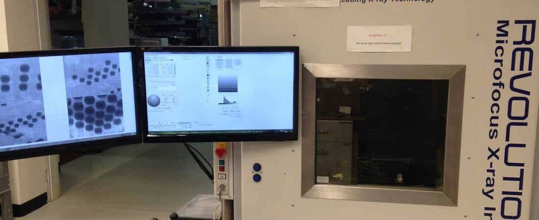
Keep the image, location and criterion together.
Agree the report format and image retention before inspection. The evidence should distinguish what is observed from what is inferred.
- Inspection object
- Board/revision, serial or lot, component reference and inspected joint/region.
- Method and views
- Equipment/setup identification as required, view orientation and applicable imaging conditions.
- Finding and metric
- Annotated image, region definition, reported measurement and the relevant acceptance limit.
- Interpretation and status
- Confirmed condition, uncertain indication, further work needed and authorized final disposition.
No universal void percentage applies to every joint.
Specify the governing package, application and customer criteria. A percentage calculated from a projected image area is not automatically a three-dimensional void-volume percentage. X-ray evidence also does not establish component value, firmware or circuit operation; those remain separate test requirements.
X-Ray Inspection FAQs
Find answers about inspection methods, reports and approvals before placing your order.
Can X-ray replace AOI?
Not completely. Optical and X-ray methods reveal different features. Define which visible and internal requirements each method covers rather than treating either as universal. [S21] [S25]
Is every apparent dark or light region a defect?
No. Interpretation depends on the materials, overlap, orientation and imaging conditions. Review the indication against the selected method and acceptance criteria before assigning a defect.
Is a twenty-five-percent void limit always correct?
No universal percentage should be copied into every order. Agree the applicable joint type, region definition, measurement method and acceptance criteria for the product.
Does 2D X-ray prove a joint is free of head-in-pillow?
Do not assume so. Certain interfaces or orientations may not be conclusive in a projection image. Additional views, suitable 3D methods or destructive analysis may be needed. [S25] [S26]
Is X-ray the same as microsection analysis?
No. Microsection exposes a physical internal plane by removing material. It may be used when an internal feature remains unresolved, but it consumes the selected specimen. [S33]
Can a passed X-ray inspection replace functional testing?
No. An image of the joint structure is not a measurement of the assembly’s powered response. Define functional verification separately when required.
Connect the next part of your quality plan.
Technical references
- [S21]Koh Young — Zenith S 3D AOI
- [S25]Nordson — Automated X-ray Inspection Product Portfolio (PDF)
- [S26]Nordson — MATRIX X-Series SMT X-ray Inspection Datasheet (PDF)
- [S33]Leica Microsystems — Cross-section quality control of electronics
Explore the inspection and testing references below. Include the applicable standards, acceptance criteria and required records with your enquiry so we can confirm the inspection plan for your board.