PCB DFM Check
Find fabrication questions before they become production changes. Review the board data against the intended stackup, processes and acceptance requirements.
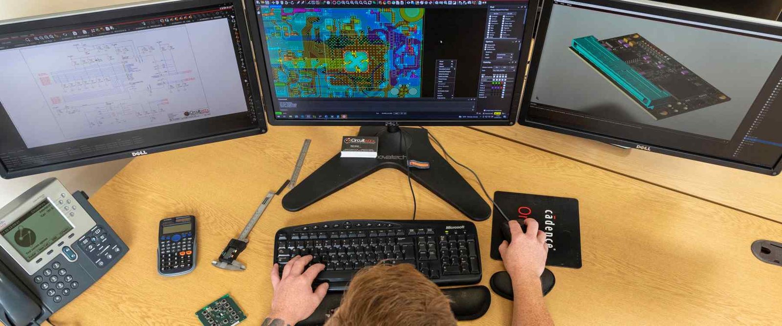
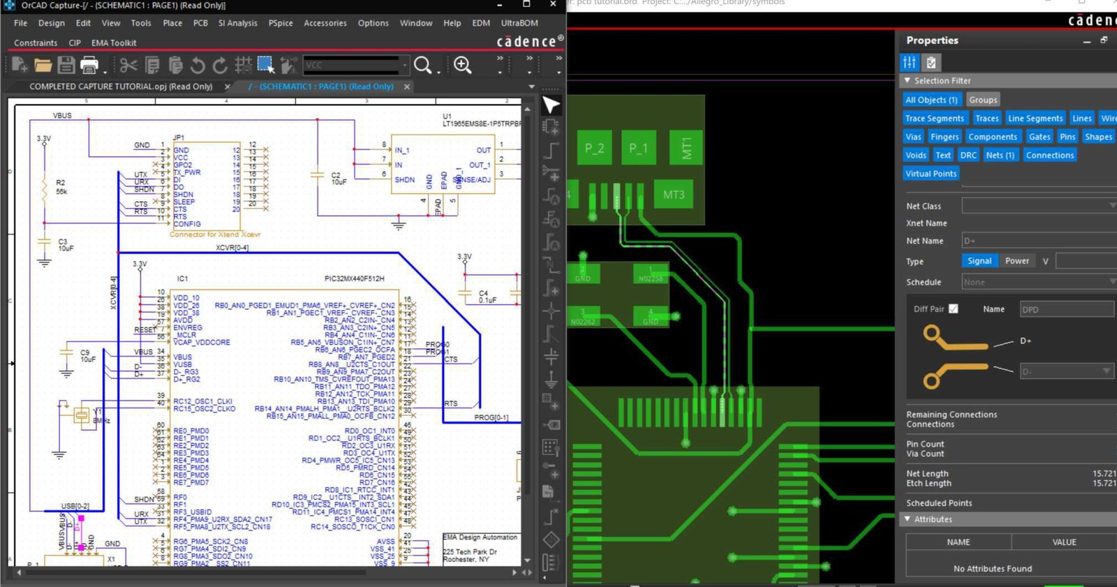
Turn design data into a clear fabrication baseline.
A PCB design-for-manufacturing check examines whether fabrication data is compatible with the proposed manufacturing process. Manufacturer-specific constraints matter: a layout that passes its internal design rules can still need changes for the selected construction. [S04] [S06]
For a GlobalWellPCB review, identify the dimensions that are fixed and those that may be adjusted with approval. The useful output is not simply a green checkmark; it is a resolved issue list and a fabrication package everyone can identify.
Review the complete construction.
The checklist is organized by fabrication risk rather than a universal list of minimum dimensions. Final limits depend on the material, copper, stackup and process selected for the job.
Scroll the table horizontally to see all columns.
| Review area | What to evaluate | What to agree |
|---|---|---|
| File consistency | Layer order, outline, drill units, polarity, revision and fabrication notes. | Resolve missing layers, mismatched outlines and conflicting requirements. |
| Copper features | Trace/space geometry, copper-to-edge clearance and isolated features. | Identify critical locations and the proposed process allowance. |
| Holes and interconnections | Plated/non-plated designation, finished-hole intent, slots and annular-ring geometry. | Clarify tool size versus finished size and interconnection construction. |
| Stackup and lamination | Materials, copper distribution, thickness and sequential-lamination requirements. | Record the approved construction and any controlled-impedance geometry. |
| Mask and surface finish | Mask openings, registration requirements, exposed copper and finish notes. | Confirm that artwork and drawing requirements describe the same result. |
| Panel and mechanical details | Routing, scoring, tabs, rails, cutouts and bend areas where relevant. | Separate the delivered board outline from the agreed manufacturing panel. |
Tell us which features need inspection, your sampling requirements and the reports you need. We will confirm these details in your quotation.
From a clear requirement to a documented decision.
- 01
Supply the released package
Send the full fabrication dataset together, not isolated screenshots. Identify revision, units, quantities and the drawing that governs the build.
- 02
Classify the findings
Separate missing information, potential process risks and actual conflicts. Record the location and consequence so the designer can evaluate each item.
- 03
Approve a resolution
Accept a proposed change, provide corrected data or document an approved exception. Require explicit approval for changes to controlled dimensions.
- 04
Recheck the final revision
Review the updated package and close the issue list before fabrication. Preserve the accepted data and decisions for repeat orders.
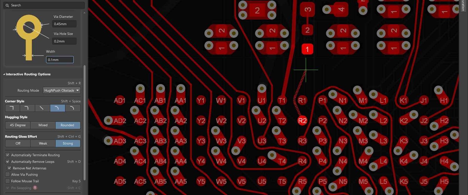
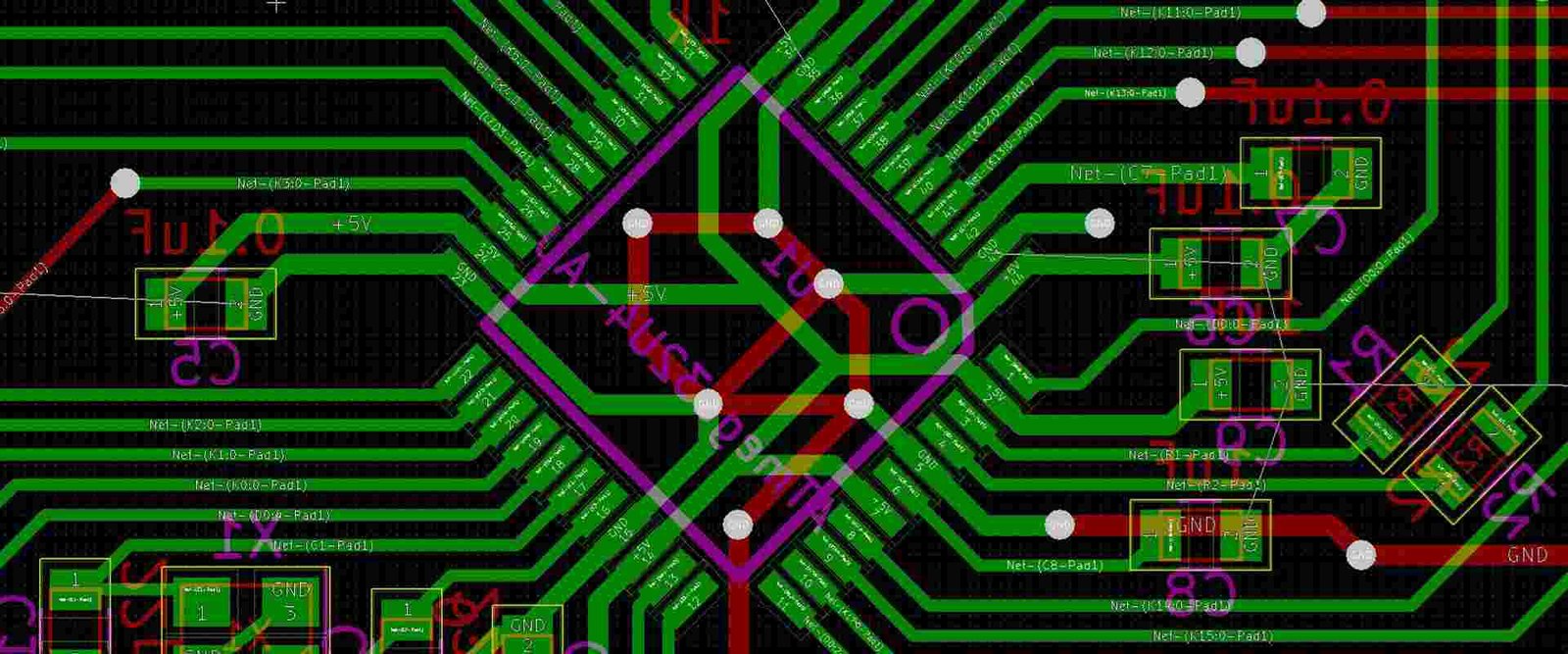
Every finding should be easy to act on.
Use this report structure for the review discussion. It keeps engineering questions separate from approved fabrication instructions.
- Issue identity
- A unique finding number, layer, coordinate or feature reference and an annotated image where useful.
- Requirement and risk
- The drawing requirement or process constraint, the observed condition and the practical concern.
- Proposed resolution
- A specific data change, clarification request or alternative construction, with effects stated.
- Approval trail
- Customer response, responsible owner, revised file identifier and closure status.
DFM does not validate circuit function.
This page focuses on bare-board manufacturability. Assembly-focused DFA and test-access planning should be treated separately. A resolved DFM review is not a signal-integrity simulation, firmware check or guarantee that the circuit meets its functional requirements. [S05]
PCB DFM Check FAQs
Find answers about inspection methods, reports and approvals before placing your order.
What is the difference between DRC and DFM?
DRC checks a layout against its configured design rules. DFM considers fabrication against the selected manufacturing constraints. The two can overlap, but an internal DRC pass does not prove that every production requirement has been addressed. [S04] [S06]
Is this a PCB layout design service?
The requested scope is a review of supplied fabrication data. New routing, circuit changes or a redesigned stackup should be identified as separate engineering work and approved explicitly.
Can you review incomplete files?
An initial discussion can identify missing inputs, but do not treat it as approval to fabricate. List assumptions and open questions until a complete, consistent revision is available.
Will manufacturing data be changed without approval?
Define the allowed CAM adjustments in the order. Changes affecting electrical, mechanical or acceptance requirements should follow the agreed approval process and be documented in the released package.
Does a DFM check include assembly risks?
Not automatically. BOM/footprint matching, placement access and assembly clearances belong in the PCBA DFA scope. Request both reviews when fabrication and assembly are ordered together. [S05]
What should I do after correcting a DFM finding?
Submit a clearly identified new revision and a response against the issue list. Ask for closure of affected findings and confirmation of the final fabrication baseline.
Connect the next part of your quality plan.
Technical references
Explore the inspection and testing references below. Include the applicable standards, acceptance criteria and required records with your enquiry so we can confirm the inspection plan for your board.